
Local oscillator signal generation

Active Publication Date: 2014-06-12
NXP BV
View PDF3 Cites 1 Cited by
  • Summary
  • Abstract
  • Description
  • Claims
  • Application Information

AI Technical Summary

Benefits of technology

This patent aims to reduce power consumption while also minimizing phase noise in a certain way. The technical effect of this invention is to achieve improved efficiency and performance in a certain field.

Problems solved by technology

A conventional VCO cannot typically be tuned over such a wide range of frequencies without a reduction in the phase noise performance (i.e. without an increase in the phase noise).
However, such features increase the design complexity of a frequency divider.
The higher the complexity, the more difficult it is to achieve an acceptable trade-off between noise and power consumption.
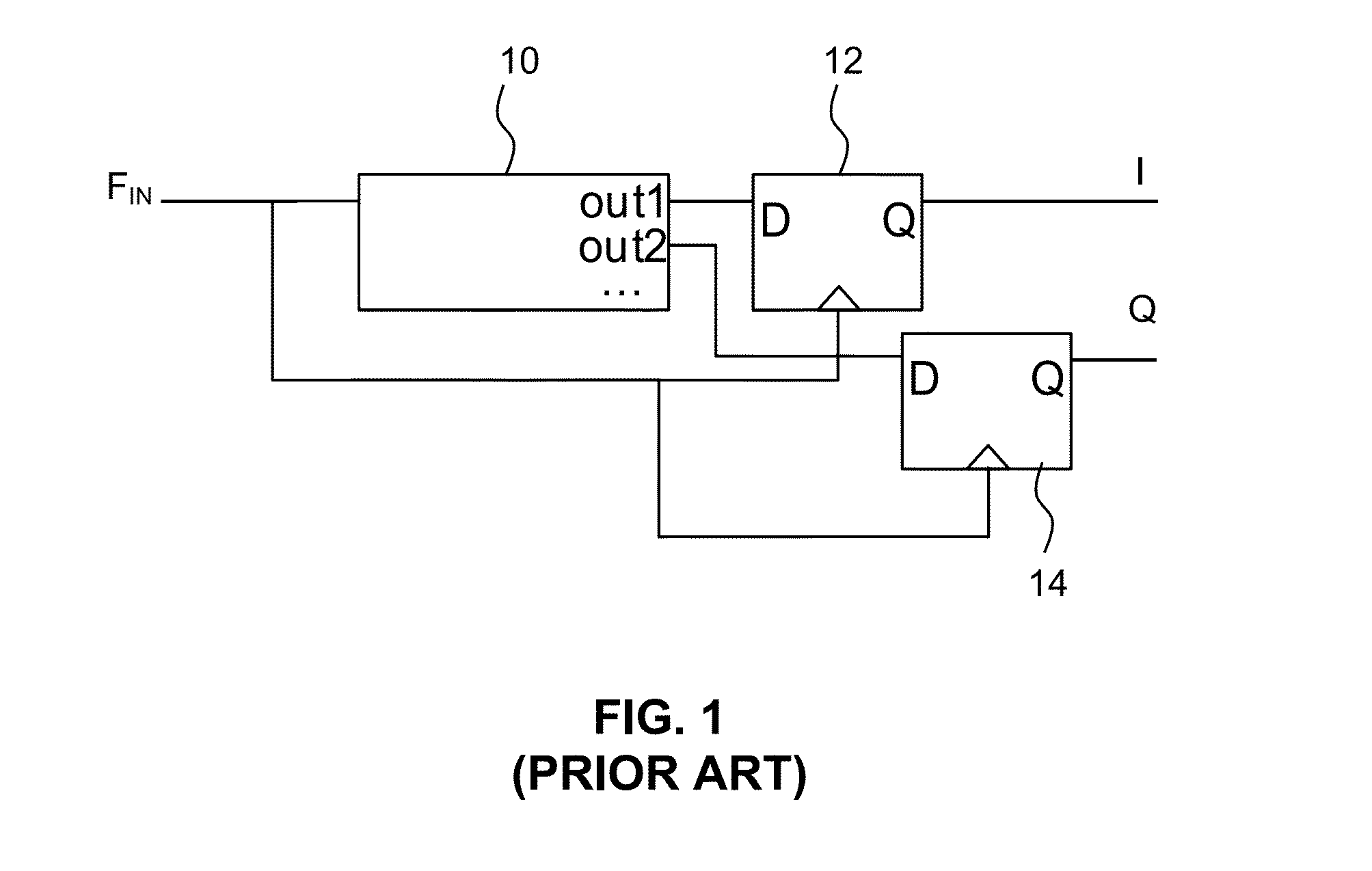
This known technique of re-clocking poses the problem of how to re-clock (i.e. “re-time” or align) the LO chain output signal with a low noise (or low jitter) high frequency reference clocking signal.

Method used


Image

  • Local oscillator signal generation
  • Local oscillator signal generation
  • Local oscillator signal generation

Examples


Embodiment Construction

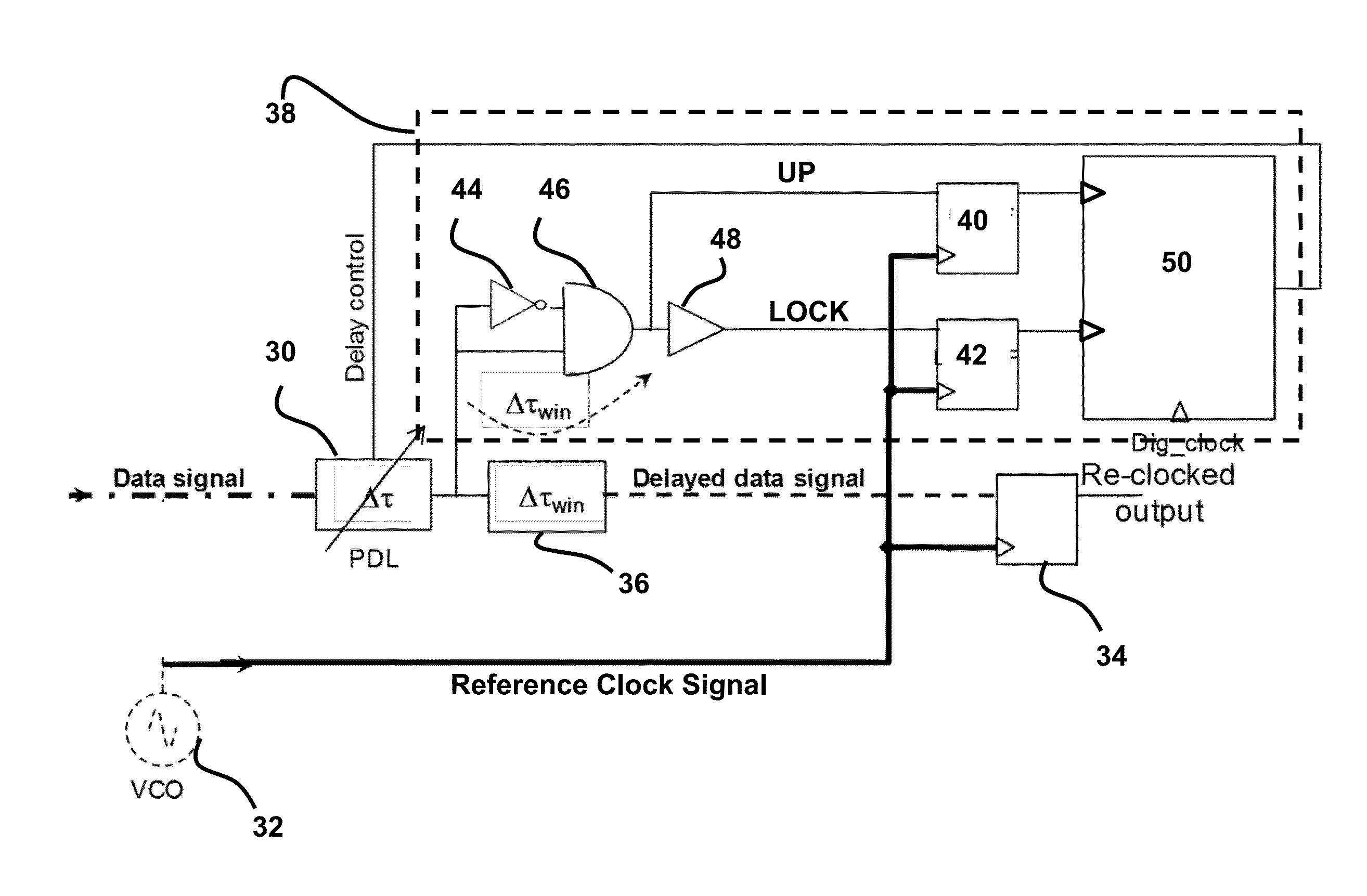
[0030]Referring to FIG. 3, there is shown a schematic block diagram of a local oscillator signal generation circuit according to an embodiment of the invention. The circuit comprises a Programmable Delay Cell (PDL) 30 adapted to delay a data signal by variable time period ΔT according to a delay control signal. Depending on the delay control signal, the PDL is adapted to delay the data signal within at least two periods of a reference clock signal that is provided to the circuit.

[0031]Here, the reference clock signal is provided from a VCO 32 and the frequency of the reference clock signal is the signal of highest frequency within the circuit. The reference clock signal is provided to the clock input terminal of a data flip-flop 34, thus acting as the clock signal for the data flip-flop.

[0032]The delayed data signal provided by the PDL is passed through an additional fixed delay unit 36 (which further delays the delayed data signal by a fixed time period of ΔTwin) to the data input ...


PUM


Abstract

A local oscillator signal generation circuit is presented. The circuit comprises: a delay device adapted to delay a data signal according to a control signal; a data flip-flop having the delayed data signal provided to its data input terminal and a reference clocking signal provided to its clock input terminal; and a control circuit adapted to generate first and second partially overlapping pulse windows from the delayed data signal and to generate a control signal based on the first and second partially overlapping pulse windows and the reference clocking signal. The control signal is provided to the delay device to control the amount by which the data signal is delayed so as to align the rising edges of the data signal and the reference clock signal. A local oscillator signal is derived from the output of the data flip-flop.

Description

FIELD OF THE INVENTION [0001]This invention relates to the field of electronic circuits, and more particularly to the generation of a local oscillator signal by means of an electronic circuit such as a frequency divider circuit.BACKGROUND [0002]Radio Frequency (RF) transceivers are mainly used to shift a RF input spectrum down in frequency in order to reduce the sampling frequency of digital channel decoders.[0003]Frequency division is a well-known concept, especially in the field of telecommunications, which may be used to reduce the frequency of a signal.[0004]Such frequency division is typically used in the generation of a Local Oscillator (LO) signal and makes use of a mixer which employs a LO as a frequency selector. The spectral purity of the LO can be an important consideration for effective RF signal reception.[0005]A parameter typically used to quantify the spectral purity of a LO is the phase noise (expressed in dB / Hz), wherein a good LO signal will have a low phase noise....

Claims


Application Information

Patent Timeline
IPC IPC(8): H03K3/037H03B19/00
CPCH03L7/0812H03B19/00H03K3/037
Inventor TOURRET, JEAN-ROBERT
Owner NXP BV
Learn More