Cooling device and electronic device made therewith
a technology of electronic devices and cooling devices, which is applied in the direction of domestic cooling devices, lighting and heating devices, and semiconductor/solid-state device details, etc., can solve the problems of deteriorating cooling performance and achieve the effect of sufficient cooling performan
- Summary
- Abstract
- Description
- Claims
- Application Information
AI Technical Summary
Benefits of technology
Problems solved by technology
Method used
Image

Examples
first exemplary embodiment
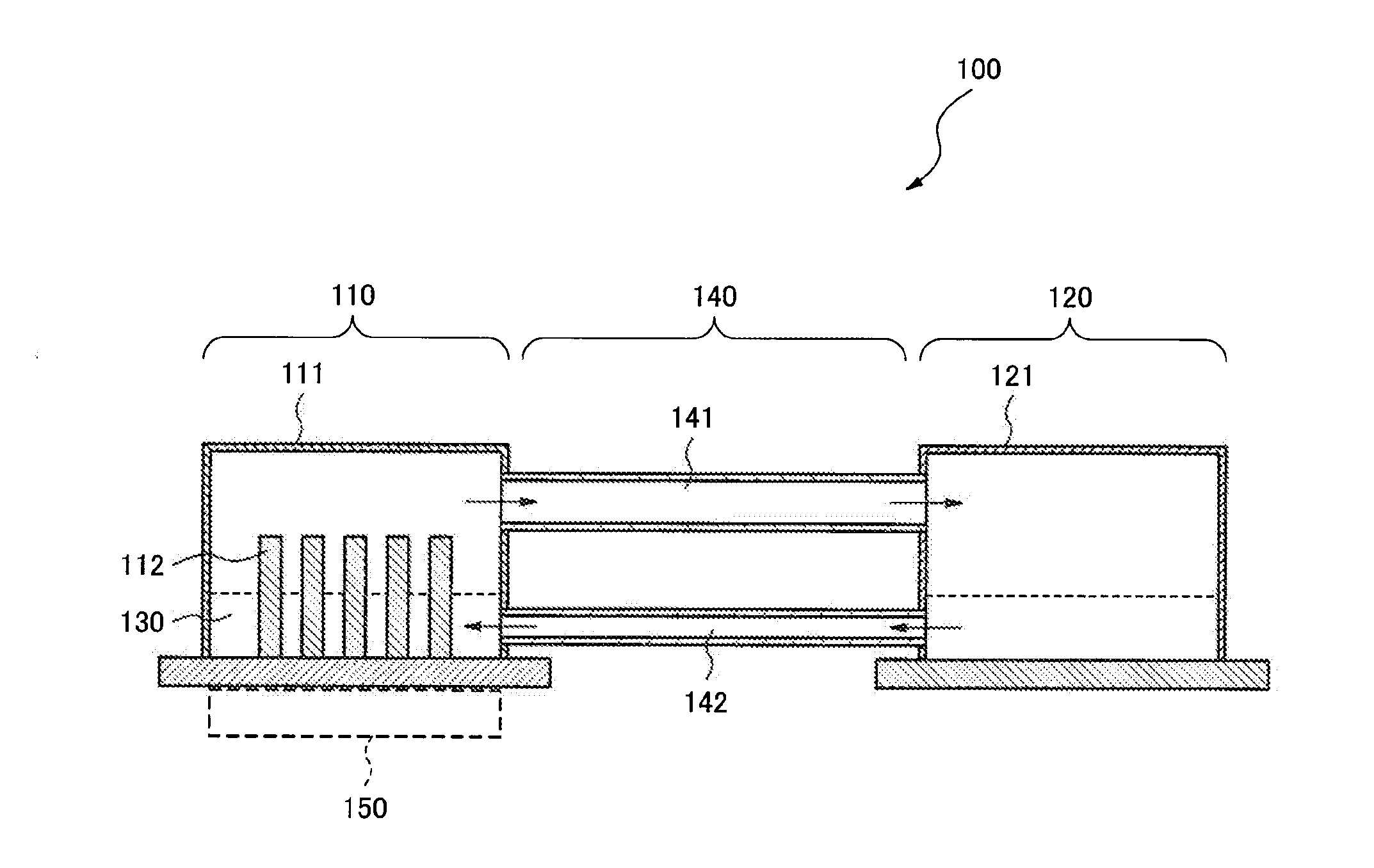
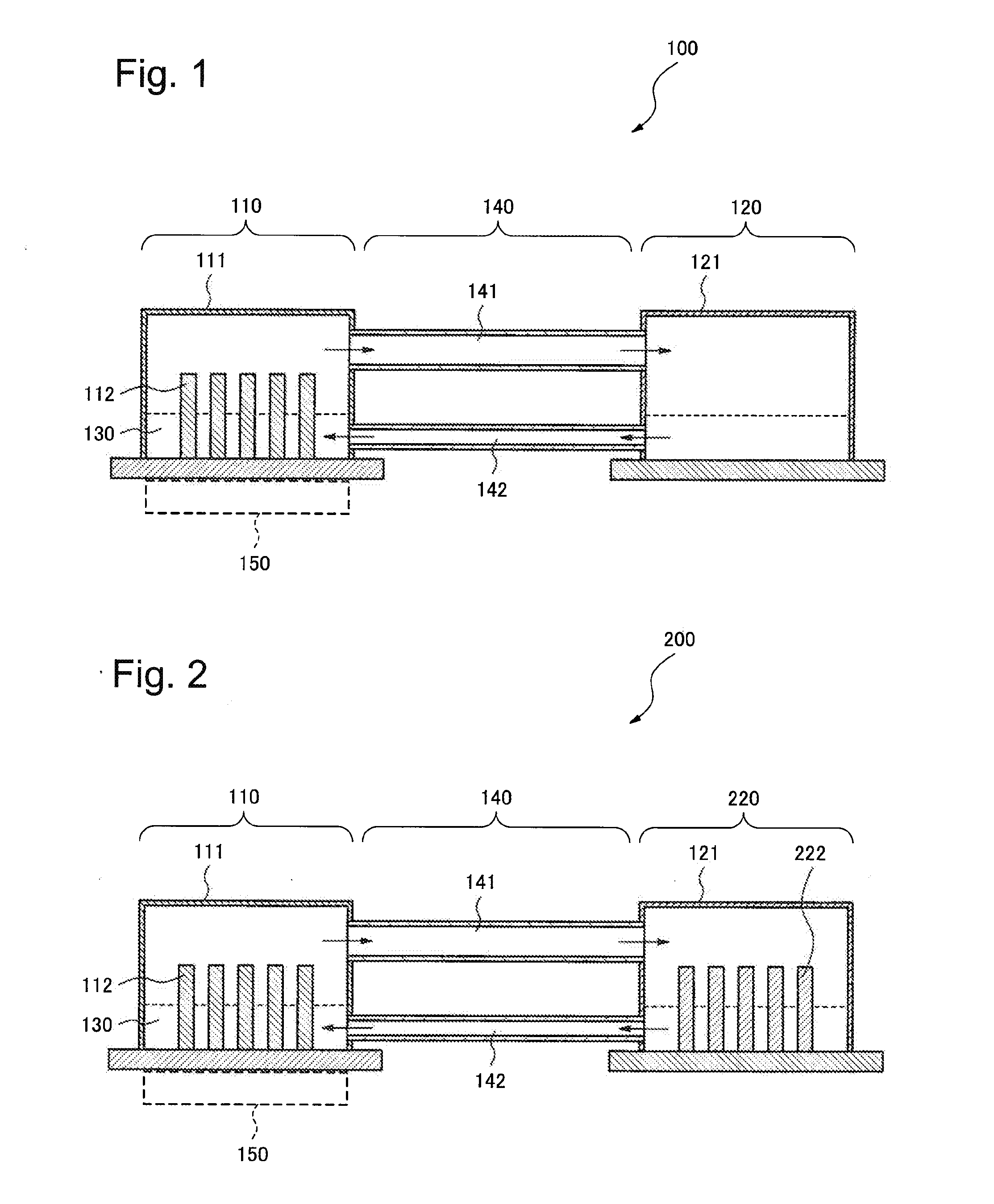
[0056]FIG. 1 is a cross-sectional side view showing a configuration of a cooling device 100 according to the first exemplary embodiment of the present invention. The cooling device 100 includes an evaporation unit 110 which stores refrigerant 130, a condensation unit 120 which performs heat radiation by condensing and liquefying the refrigerant in vapor phase (vapor-phase refrigerant) which was vaporized at the evaporation unit 110, and piping 140 which connects the evaporation unit 110 with the condensation unit 120. Here, the evaporation unit 110 and the condensation unit 120 are located at approximately the same height in the vertical direction. The evaporation unit 110 includes an evaporation container 111 and a partition wall section 112 which is arranged within the evaporation container 111 and partitions the refrigerant 130, where the height of the partition wall section 112 is equal to or larger than that of the vapor-liquid interface of the refrigerant 130 and is smaller th...
second exemplary embodiment
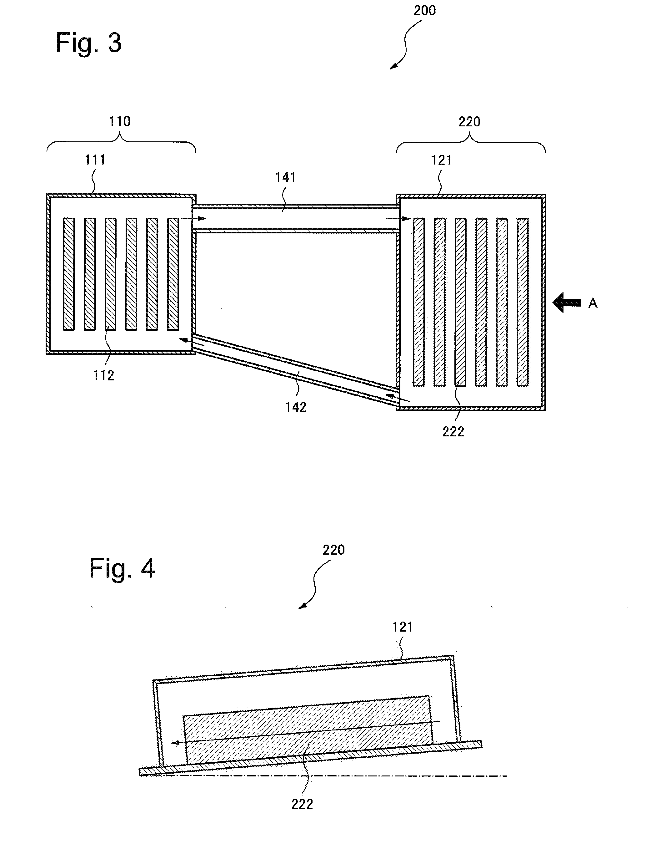
[0076]Next, a second exemplary embodiment of the present invention will be described. FIG. 2 is a cross-sectional side view showing a configuration of a cooling device 200 according to the second exemplary embodiment of the present invention, and FIG. 3 is its cross-sectional plan view. The cooling device 200 comprises the evaporation unit 110 which stores the refrigerant 130, a condensation unit 220 which performs heat radiation by condensing and liquefying vapor-phase refrigerant which was vaporized at the evaporation unit 110, and the piping 140 which connects the evaporation unit 110 with the condensation unit 220. Here, the evaporation unit 110 and the condensation unit 220 are located at approximately the same height in the vertical direction. The evaporation unit 110 comprises the evaporation container 111 and the partition wall section 112 which is arranged within the evaporation container 111 and partitions the refrigerant 130, where the height of the partition wall section...
third exemplary embodiment
[0083]Next, a third exemplary embodiment of the present invention will be described. FIGS. 6A and 6B are diagrams showing a configuration of a cooling device 300 according to the third exemplary embodiment of the present invention, where FIG. 6A is its cross-sectional side view and FIG. 6B is its cross-sectional view taken on the line b-b in FIG. 6A. The cooling device 300 includes the evaporation unit 110 which stores the refrigerant 130, the condensation unit 220 which performs heat radiation by condensing and liquefying vapor-phase refrigerant which was vaporized at the evaporation unit 110, and the piping 140 which connects the evaporation unit 110 with the condensation unit 220. Here, the evaporation unit 110 and the condensation unit 220 are located at approximately the same height in the vertical direction. The evaporation unit 110 includes the evaporation container 111 and the partition wall section 112 which is arranged within the evaporation container 111 and partitions th...
PUM
 Abstract
Description
Claims
Application Information
 - Generate Ideas
- Intellectual Property
- Life Sciences
- Materials
- Tech Scout
- Unparalleled Data Quality
- Higher Quality Content
- 60% Fewer Hallucinations
Browse by: Latest US Patents, China's latest patents, Technical Efficacy Thesaurus, Application Domain, Technology Topic, Popular Technical Reports.
© 2025 PatSnap. All rights reserved.Legal|Privacy policy|Modern Slavery Act Transparency Statement|Sitemap|About US| Contact US: help@patsnap.com