Co2 capture processes using rotary wheel configurations

a technology of rotary wheels and capture processes, applied in separation processes, hydrogen sulfides, sulfur compounds, etc., can solve the problems of capital and energy intensive traditional approaches, and achieve the effects of reducing sorption capacity, increasing heat management, and serving to remove hea

Inactive Publication Date: 2014-06-26
EXXON RES & ENG CO
View PDF7 Cites 29 Cited by
  • Summary
  • Abstract
  • Description
  • Claims
  • Application Information

AI Technical Summary

Benefits of technology

[0012]Adsorption can tend to lead to the generation of heat. Rising temperature in the solid monolithic sorbent(s) can tend to reduce sorption capacity. The integration of additional cooling mechanisms to combat adiabatic temperature increases can be effected, e.g., by injection of atomized liquid droplets or sprays or running liquid streams through the sorbent bed or monolith channels. This liquid can advantageously serve to remove heat by vaporization and/or through sensib

Problems solved by technology

This traditional approach is

Method used


Image

  • Co2 capture processes using rotary wheel configurations
  • Co2 capture processes using rotary wheel configurations
  • Co2 capture processes using rotary wheel configurations

Examples


embodiment 1

[0066]A method for enhanced control, separation, and / or purification of CO2 gas from one or more sources having a mixture of gases (and / or carbonaceous liquids having sufficient vapor pressure), the method comprising: providing at least two solid monolithic sorbents having a selectivity for the CO2 gas in a continuous or semi-continuous, cyclic, countercurrent sorption-desorption process involving at least steps of first and second CO2 sorption, sorbent heating, first and second CO2 desorption, and sorbent cooling; in the first CO2 sorption step, exposing the mixed gas source(s), which contain(s) CO2 gas at a first temperature, to the solid monolithic sorbents, which are at a second temperature that is at least about 15° C. higher (e.g., at least about 30° C. higher) than the first temperature, as well as under further conditions sufficient for the solid monolithic sorbents to selectively adsorb the desired CO2 gas, thus forming at least partially, selectively CO2-sorbed solid monol...

embodiment 2

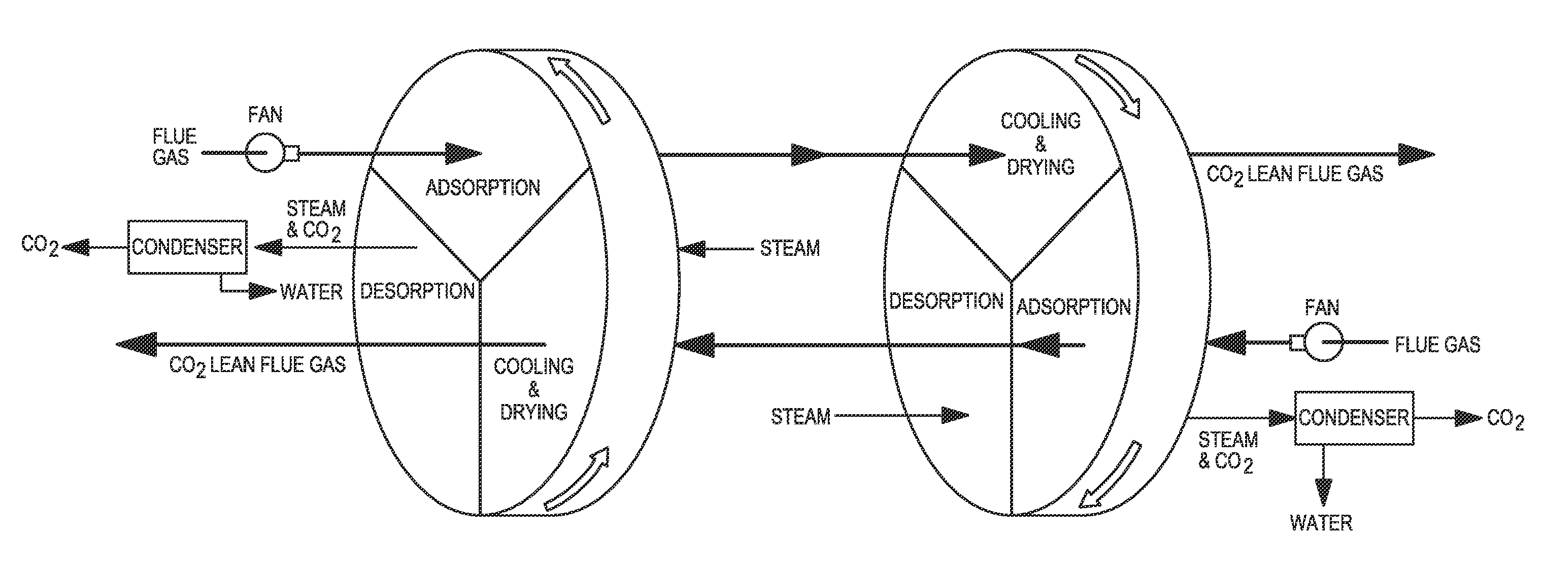
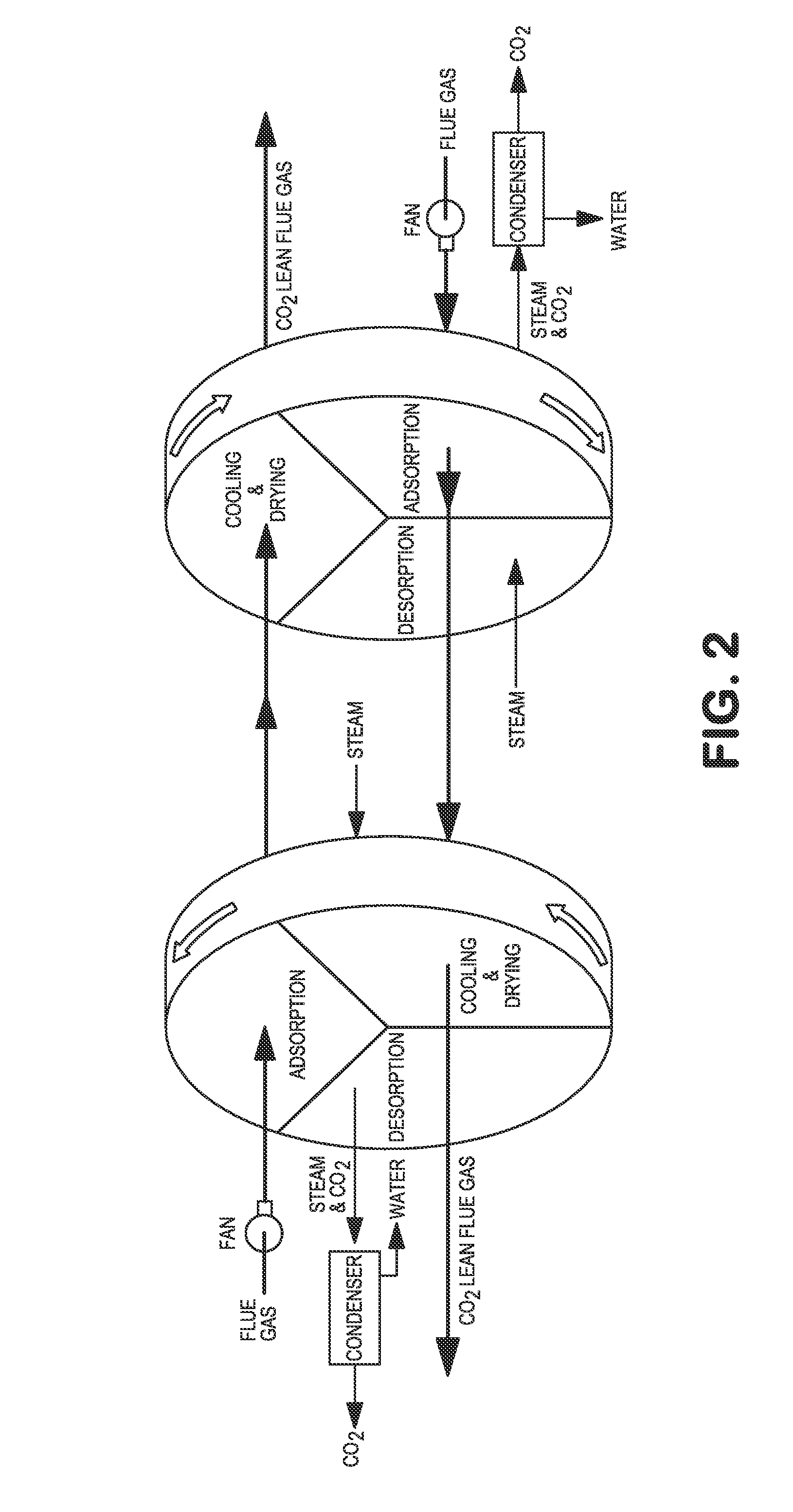
[0067]The method of embodiment 1, wherein the at least two solid monolithic sorbents are oriented such that their cross-sectional planes are approximately parallel and such that they rotate about a common rotational axis that is substantially perpendicular to the cross-sectional planes of the monolithic sorbents, with each successive solid monolithic sorbent having counter-rotational directions that alternate between clockwise and counterclockwise, as viewed along the common rotational axis.

embodiment 3

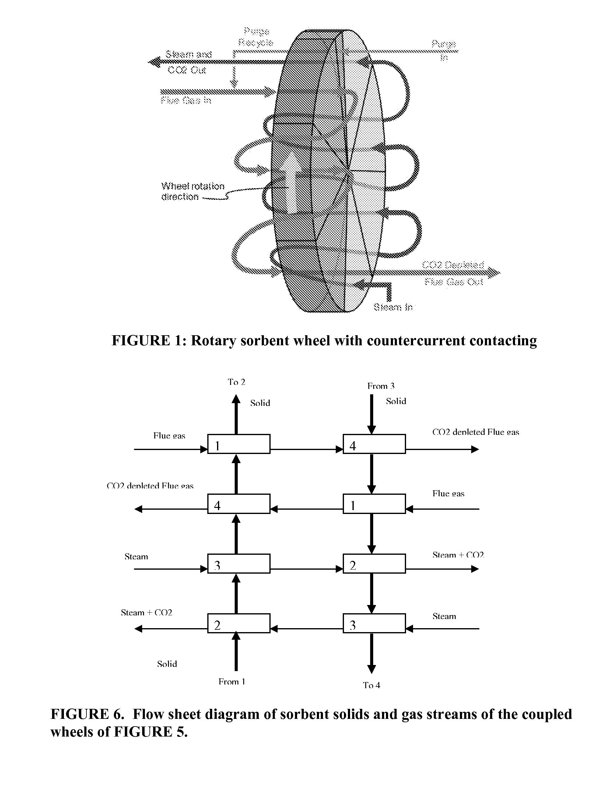
[0068]The method of embodiment 1 or embodiment 2, comprising two solid monolithic sorbents, a first and a second, and thus two sets of streams for each step, also a first and a second, wherein: in the first CO2 sorption step, the first mixed gas source is exposed to the first solid monolithic sorbent to form the first at least partially CO2-sorbed solid monolithic sorbent and the first at least partially CO2-depleted product stream, and the second mixed gas source is exposed to the second solid monolithic sorbent to form the second at least partially CO2-sorbed solid monolithic sorbent and the second at least partially CO2-depleted product stream; the first at least partially CO2-depleted product stream from the first CO2 sorption step is then exposed to the second cooled and optionally dried monolithic sorbent in the second CO2 sorption step, thus forming the second further CO2-depleted product stream, and the second at least partially CO2-depleted product stream from the first CO2...


PUM

PropertyMeasurementUnit
Temperatureaaaaaaaaaa

Abstract

The disclosure relates to a continuous or semi-continuous, cyclic, countercurrent sorption-desorption method for enhanced control, separation, and/or purification of CO2 from one or more sources of a mixture of gases (and/or carbonaceous liquids that have sufficient vapor pressure) through integrated use of solid monolithic sorbents having a selectivity for sorption of the CO2.

Description

CROSS-REFERENCE TO RELATED APPLICATIONS[0001]This application claims the benefit of U.S. Application Ser. No. 61 / 740,025, filed on Dec. 20, 2012; which is incorporated by reference herein in its entirety.FIELD OF THE INVENTION[0002]This invention relates to methods for enhanced control, separation, and / or purification of CO2 from one or more sources of a mixture of gases in a continuous or semi-continuous, cyclic sorption-desorption process.BACKGROUND OF THE INVENTION[0003]Global climate change concerns may necessitate capture of CO2, e.g., from flue gases and other process streams. One traditional approach involves absorption of CO2 with an amine solution, such as monoethanolamine (MEA), other ethanolamines, or certain amine mixtures, which solution is then thermally regenerated and recycled. This traditional approach is capital and energy intensive. There is considerable prior art in this area of conventional liquid sorption.[0004]There is also some level of prior art regarding so...

Claims


Application Information

Patent Timeline
IPC IPC(8): B01D53/14C07C7/12
CPCB01D53/0462B01D53/06B01D2253/342B01D2257/504B01D2259/40022B01D2259/40045B01D2259/40064B01D2259/40066B01D2259/40067B01D2259/40069Y02C20/40C07C7/12
Inventor GUPTA, RAMESHTHOMANN, HANSLENZ, RICHARD D.CARAM, HUGO S.
Owner EXXON RES & ENG CO
Why Eureka
Try Eureka