Al technical title is built by PatSnap Al team. It summarizes the technical point description of the patent document.
a multi-scale, telescopic technology, applied in the field of wide field of view imaging systems, can solve the problems of image distortion, aberration, speckle, etc., and achieve the effect of reducing the magnitude of a first localized aberration
Active Publication Date: 2014-06-26
DUKE UNIV
View PDF8 Cites 47 Cited by
Summary
Abstract
Description
Claims
Application Information
AI Technical Summary
This helps you quickly interpret patents by identifying the three key elements:
Problems solved by technology
Method used
Benefits of technology
[0021]Another embodiment of the present invention is a multiscale telescopic imaging system comprising: an objective lens, the objective lens being operative for forming a first image of a scene at a first image surface, and the objective lens including at least one reflective surface; and a plurality of microcameras, each microcamera being operative for reducing the magnitude of a first loca
Problems solved by technology
Unfortunately, turbulent mixing (caused by effects such as different temperature layers, wind speeds, etc.) can perturb the optical refractive index of the Earth's atmosphere.
As a result, as light waves travel through the atmosphere, they can become distorted, leading to image distortions (e.g., aberrations, speckle, etc.) that manifest as optical effects like the blurring and twinkling of stars when viewed from the Earths' surface.
They can also lead to impaired image resolution for space-based imaging systems used for aerial surveillance.
Unfortunately, a larger a
Method used
Image
Click on the blue label to locate the original text in one second.
Reading with bidirectional positioning of images and text.
Examples
Embodiment Construction
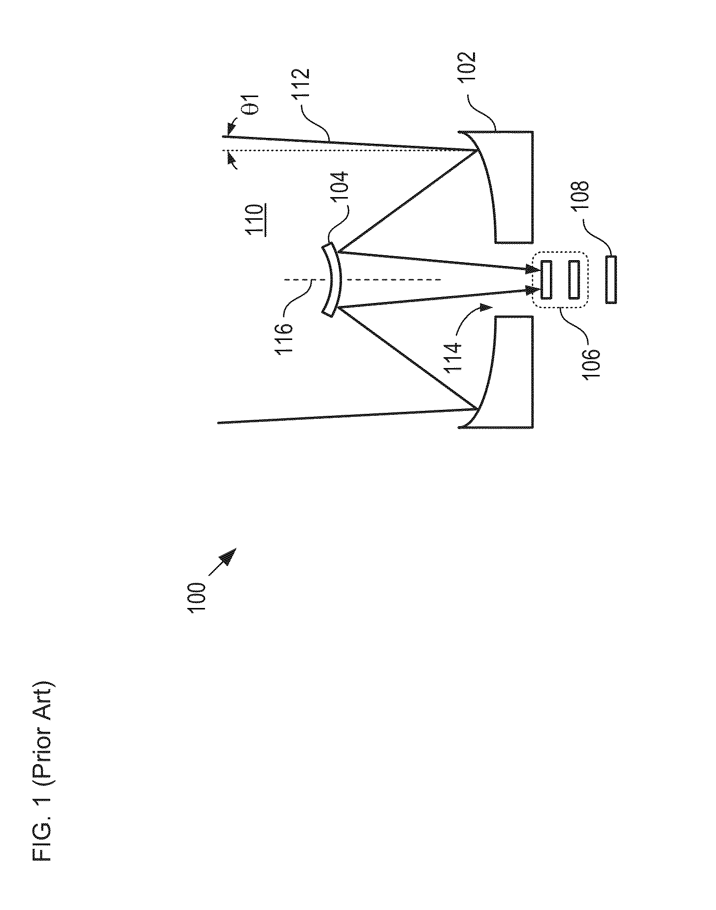
[0059]FIG. 1 depicts a schematic drawing of a cross-sectional view of a telescopic imaging system in accordance with the prior art. Imager 100 comprises primary mirror 102, secondary mirror 104, focusing system 106, and focal plane array 108. Imager 100 forms an image of a portion of scene 110. Imager 100 is representative of restricted-view, large-aperture telescopes, such as the Sloan Digital Sky Survey telescope, designed to generate a map of the entire sky. Image 100 combines employs a wide aperture to enable astronomical surveys that include stellar and galactic objects, as well as near-earth objects (e.g., low-earth satellites, space debris, etc.).
[0060]Primary mirror 102 is a 2.5-m diameter concave mirror that includes hole 114. Primary mirror 102 has a substantially symmetric shape about axis of rotation 116. Mirror 102 receives light rays 112 from scene 110 and reflects them to secondary mirror 104.
[0061]Secondary mirror 104 is a 1.08-m diameter convex mirror having a subst...
PUM
Abstract
A multiscale telescopic imaging system is disclosed. The system includes an objective lens, having a wide field of view, which forms an intermediate image of a scene at a substantially spherical image surface. A plurality of microcameras in a microcamera array relay image portions of the intermediate image onto their respective focal-plane arrays, while simultaneously correcting at least one localized aberration in their respective image portions. The microcameras in the microcamera array are arranged such that the fields of view of adjacent microcameras overlap enabling field points of the intermediate image to be relayed by multiple microcameras. The microcamera array and objective lens are arranged such that light from the scene can reach the objective lens while mitigating deleterious effects such as obscuration and vignetting.
Description
CROSS REFERENCE TO RELATED APPLICATIONS[0001]This case is a continuation-in-part of co-pending U.S. patent application Ser. No. 13 / 889,007, filed May 7, 2013 (Attorney Docket: 525-004US2), which is a continuation-in-part of U.S. patent application Ser. No. 13 / 095,407 (Attorney Docket: 525-004US) filed Apr. 27, 2011, which is a continuation-in-part of U.S. patent application Ser. No. 12 / 651,894 (now U.S. Pat. No. 8,259,212), filed 4 Jan. 2010 (Attorney Docket: 524-005US), which claims priority of U.S. Provisional Patent Application 61 / 142,499, filed Jan. 5, 2009 (Attorney Docket: 524-002US), each of which is incorporated herein by reference.[0002]This application also claims priority of provisional patent applications U.S. Ser. No. 61 / 720,469, filed Oct. 31, 2012 (Attorney Docket: DU4043PROV) and U.S. Ser. No. 61 / 774,910, filed Mar. 8, 2013 (Attorney Docket: DU4043PROV-2), each of which is incorporated herein by reference.[0003]If there are any contradictions or inconsistencies in la...
Claims
Application Information
Patent Timeline
Application Date:The date an application was filed.
Publication Date:The date a patent or application was officially published.
First Publication Date:The earliest publication date of a patent with the same application number.
Issue Date:Publication date of the patent grant document.
PCT Entry Date:The Entry date of PCT National Phase.
Estimated Expiry Date:The statutory expiry date of a patent right according to the Patent Law, and it is the longest term of protection that the patent right can achieve without the termination of the patent right due to other reasons(Term extension factor has been taken into account ).
Invalid Date:Actual expiry date is based on effective date or publication date of legal transaction data of invalid patent.