Swing-style and high signal-to-noise ratio demodulation devices and corresponding demodulation method for the measurement of low coherence interference displacement

Inactive Publication Date: 2014-06-26
TIANJIN UNIV
View PDF4 Cites 7 Cited by
  • Summary
  • Abstract
  • Description
  • Claims
  • Application Information

AI Technical Summary

Benefits of technology

[0004]This invention aims to overcome the deficiencies of the previous arts, and to provide a swing-style and high signal-to-noise ratio low coherence interference demodulation device and the corresponding demodulation method for the measurement of displacement. The demodulation technique has all the advantages of traditional time and space scanning methods

Problems solved by technology

The time scanning method is capable of measuring displacement in a large scope, but its long-term reliability and stability is poor.
In addition, the accuracy of the obtained d

Method used


Image

  • Swing-style and high signal-to-noise ratio demodulation devices and corresponding demodulation method for the measurement of low coherence interference displacement
  • Swing-style and high signal-to-noise ratio demodulation devices and corresponding demodulation method for the measurement of low coherence interference displacement
  • Swing-style and high signal-to-noise ratio demodulation devices and corresponding demodulation method for the measurement of low coherence interference displacement

Examples


embodiment 1

The First Swing-Style and High Signal-to-Noise Ratio Low Coherence Interference Demodulation Device for the Measurement of Displacement

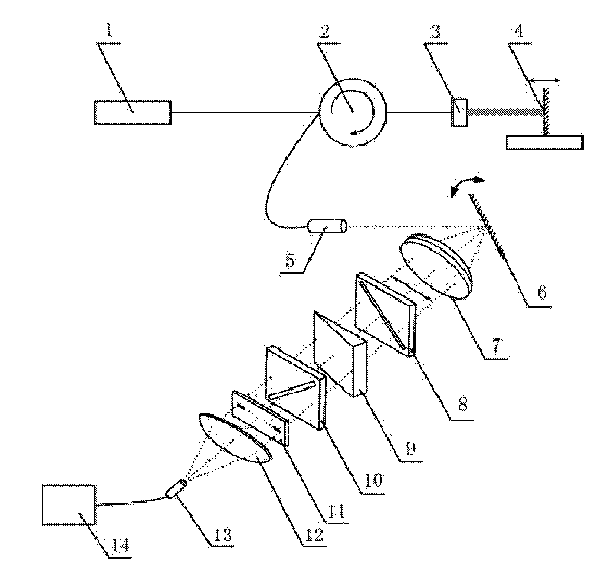
[0023]As shown in FIG. 1, the light from the broadband light source 1 passes through the optical circulator 2 and arrives at the GRIN lens 3.

[0024]Part of the light is reflected by the coated end surface of the GRIN lens 3, and the other part goes to the fixed mirror 4 installed on the test object. The two reflected light beams later are combined into one beam by optical fiber.

[0025]After passing through the optical circulator 2, part of the reflected light travels to collimating device 5 and turns into a thin light beam. The thin light beam is reflected by the rotating mirror 6 and travels through the f-θ lens 7, in which the reflection point of the rotating mirror 6 coincides with the focus of the f-θ lens 7.

[0026]By swinging the rotating mirror 6, the thin beam scans along the longitudinal direction of the narrow strip shaped birefringent wedge 9....

embodiment 2

The Second Swing-Style and High Signal-to-Noise Ratio Low Coherence Demodulation Device for the Measurement of Interference Displacement

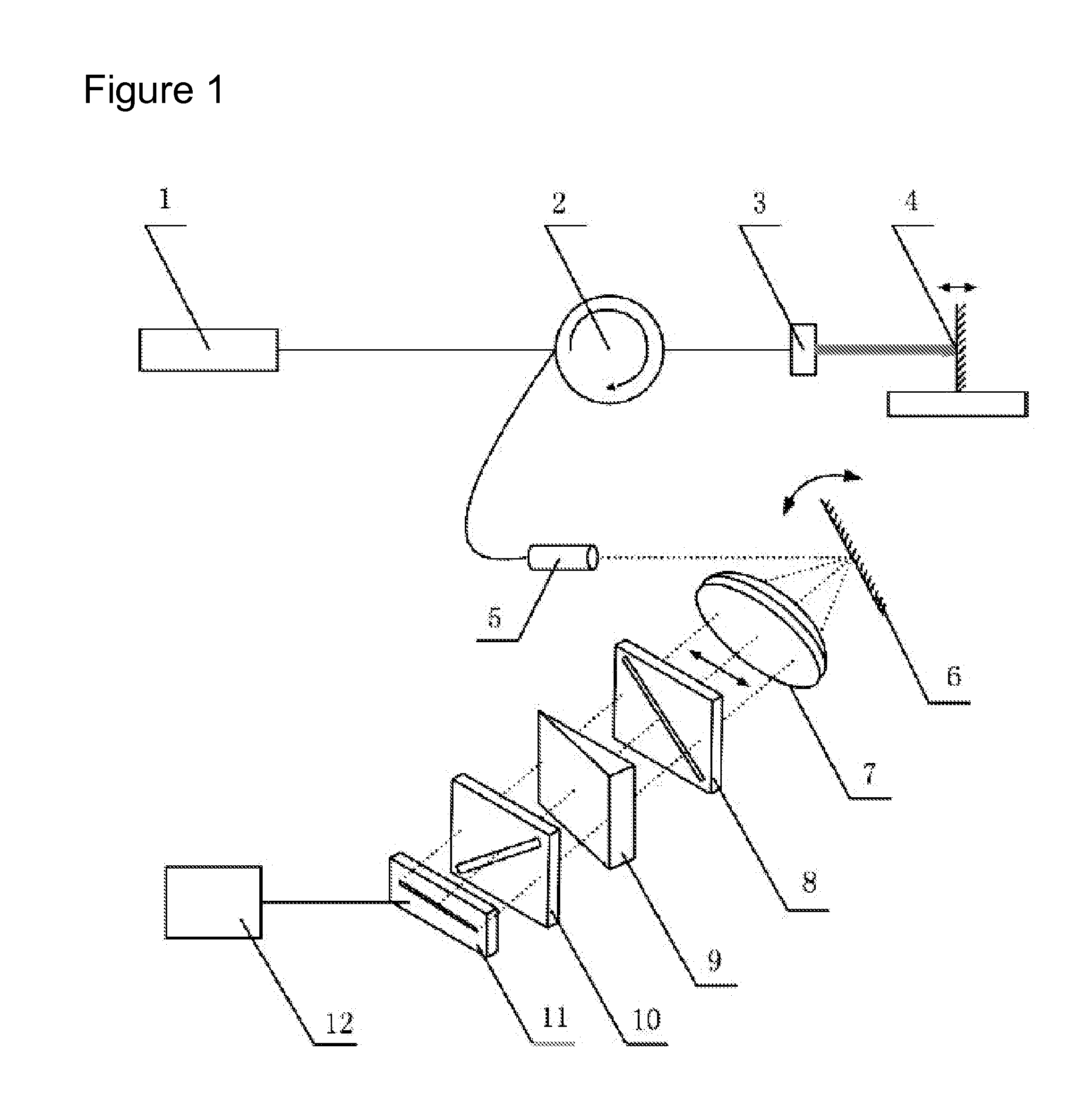
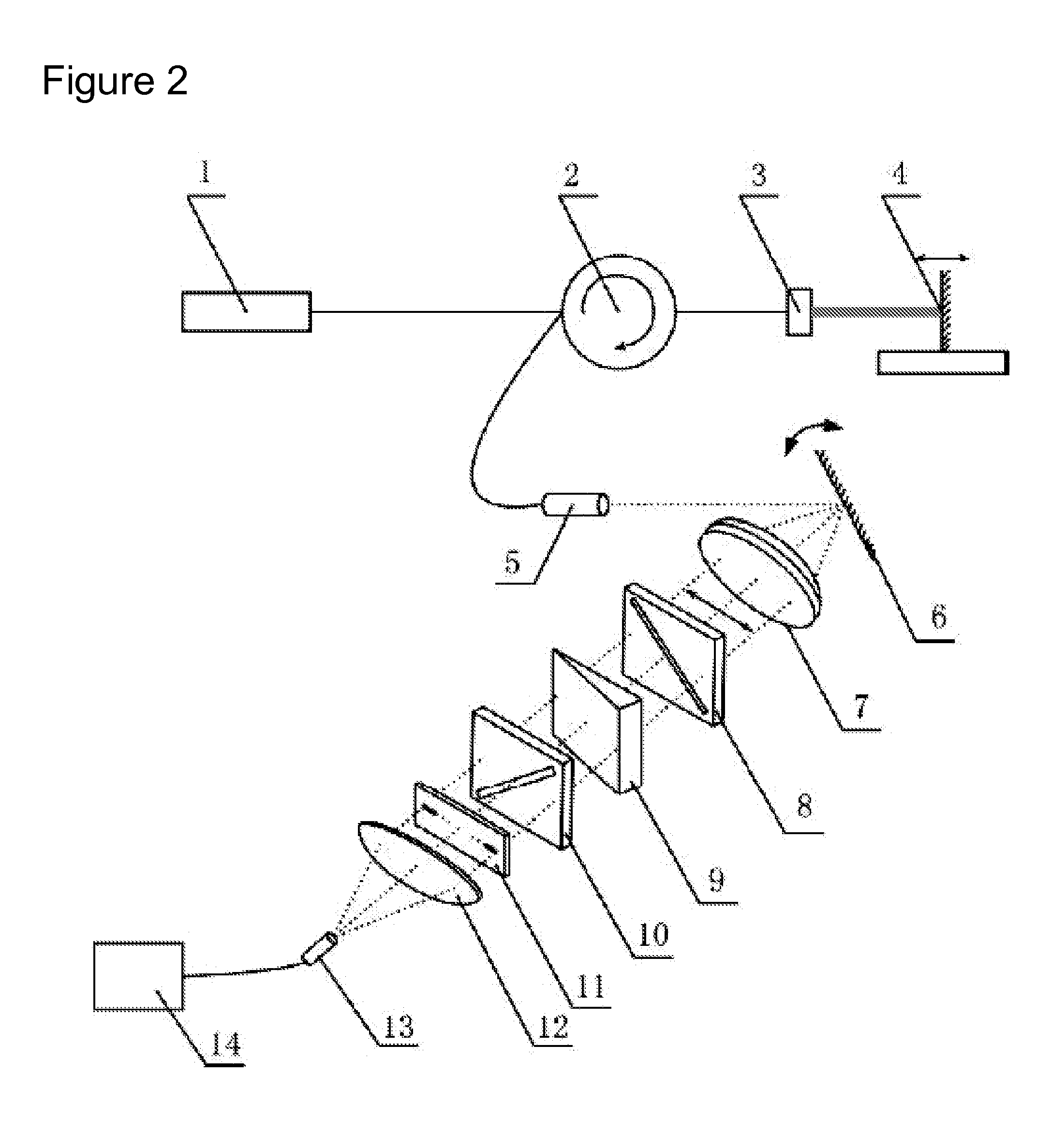
[0029]As shown in FIG. 2, the light from the broadband light source 1 passes through the optical circulator 2 and arrives at the GRIN lens 3.

[0030]Part of the light is reflected by the coated end surface of the GRIN lens 3, and the other part goes to the fixed mirror 4 installed on the test object. The two reflected light beams later are combined into one beam by optical fiber.

[0031]After passing through the optical circulator 2, part of the reflected light travels to collimating device 5 and turns into a thin light beam. The thin light beam is reflected by the rotating mirror 6 and travels through the f-θ lens 7, in which the reflection point of the rotating mirror 6 coincides with the focus of the f-θ lens 7.

[0032]By swinging the rotating mirror 6, the thin beam scans along the longitudinal direction of the narrow strip shaped birefringent wedge 9...

embodiment 3

The Demodulation Method of the Swing-Style and High Signal-to-Noise Ratio Low Coherence Interference Demodulation Devices for the Measurement of Displacement

[0037]The method of the low coherence interference demodulation device for the measurement of displacement shown in Embodiment 1 can be described as follows.

[0038]As shown in FIG. 1, light from the broadband source light 1 passes the optical circulator 2 to the GRIN lens 3. One part of the light is reflected by the coated end surface of the GRIN lens 3. The other part of the light passes the lens and arrives the reflection mirror 4 fixed on the test object. These reflected lights are coupled into optical fiber. There is an optical path difference ds between lights reflected from the coated end surface of the GRIN lens and that from the fixed mirror on the test object, where ds equals twofold of the distance between the GRIN lens 3 and fixed mirror 4.

[0039]As shown in FIG. 3, the two reflected lights form a thin light beam, after...


PUM


Abstract

This invention provides a swing-style and high signal-to-noise ratio low coherence interference demodulation devices and the corresponding demodulation method for the measurement of displacement. In the displacement sensing method, the optical path difference, which is built by the light reflections from the reference surface and the test object, varies with the displacement of the test object. When the reflected signal lights is sent to a low coherence polarization interference system, the birefringent wedge formulates a spatial distribution of optical path difference, from which the optical path difference of the reflection signals thus can be demodulated. In the displacement scanning method, the reflected signal lights are collimated and transferred to a time scanner consisting of a rotating mirror and a f-θ lens, to perform thin light beam scanning along the longitudinal direction of a birefringent wedge. This innovation provides two demodulation devices that are both applicable for the measurement methods. One uses a linear camera array and the other uses a linear micropore array and single PIN photoelectric detector, to receive interference fringes. Since the energy of the scanning beam is highly concentrated, the signal-to-noise ratio for low coherence interference signal is significantly higher than that of the traditional devices. In addition, the accuracy of these demodulation devices is significantly improved, because the linear camera array and the linear micropore array maintain a consistent spatial position of the received light spot.

Description

FIELD OF THE INVENTION[0001]This invention relates to demodulation of displacement information. The presented demodulation technique for displacement sensing information is highly accurate and applicable for the measurement of displacement, or parameters that can be converted into displacement, such as strain, temperature, thickness, group refractive index and compression stress.BACKGROUND OF THE INVENTION[0002]Low coherent interference technique for the demodulation of displacement information mainly comprises two methods, that is, time scanning and spatial scanning. In the time scanning method written by M. Song et al., (M. Song, Byoungho Lee, An effective optical evaluation technique using visible low-coherence interferometer, Optics and Lasers in Engineering, 1997, 27: 441-449), the displacement information is obtained by scanning the optical path difference of one of the arms of Michelson interferometer. In the spatial scanning method, the displacement information is converted ...

Claims


Application Information

Patent Timeline
IPC IPC(8): G01B9/02
CPCG02B5/3083G02B2207/117G01B9/0209G02B6/32G01B9/02057G02B6/29302G01B9/02065
Inventor LIU, TIEGENJIANG, JUNFENGYIN, JINDELIU, KUNWANG, SHAOHUA
Owner TIANJIN UNIV
Why Eureka
Try Eureka