Fiduciary markers and methods of placement

a fiduciary marker and marker technology, applied in the field of radiopaque fiduciary markers, can solve the problems of difficult to identically position a patient difficult to accurately target radiation, and difficult to achieve uniform positioning of patients from session to session, etc., to achieve the effect of improving the probability of retention

Inactive Publication Date: 2014-06-26
RGT UNIV OF CALIFORNIA
View PDF9 Cites 24 Cited by
  • Summary
  • Abstract
  • Description
  • Claims
  • Application Information

AI Technical Summary

Benefits of technology

[0013]In one aspect, the invention provides novel fiduciary markers that are resistant to migration from their site of implantation and which may be used to guide radio-therapeutic treatment. In another aspect, the invention provides novel delivery systems for such fiduciary markers. In another aspect, the invention provides methods of implanting markers or other materials in the body with improved probability of retention. In another aspect, the invention provides kits comprising novel markers, retention aids, and delivery devices.

Problems solved by technology

Accurate targeting of radiation is complicated by the fact that the location of various tissues within the body is not static.
Additionally, although it is attempted to keep patients in consistent poses in each treatment session, it is difficult to identically position a patient from session to session.
Unfortunately, these imaging modalities do not resolve soft tissues well.
Therefore, a radiation oncologist aiming a radiation source at a target area is often unable to directly view and locate the target area at the time of actual treatment.
As a result, the targeting of radiation is often inaccurate.
In order to increase the probability of successfully treating the target area, the treatment area is often enlarged to encompass the probable region of the target area, resulting in irradiation of healthy non-target areas (overtreatment) and a risk of missing the intended target area (undertreatment).
The treatment of bladder cancer exemplifies the difficulties of accurately targeting radiation to soft tissue areas in the body.
Unfortunately, the bladder changes shape, size, and 3-D position throughout the day from being filled and emptied of urine and due to its proximity to the bowels, which are in a constant state of movement.
Direct imaging of the tumor resection bed and the contours of the whole bladder are not possible with conebeam CT or portal imaging.
While the use of radiopaque fiduciary markers is promising, there are potential complications that result from the migration of the markers out of the area into which they have been placed.
Similar migration problems have been reported with other types of implants.
However, it is as yet unknown whether the ribbed design and scoring on these new markers will overcome the propensity of implanted markers to migrate.

Method used


Image

  • Fiduciary markers and methods of placement
  • Fiduciary markers and methods of placement
  • Fiduciary markers and methods of placement

Examples


example 1

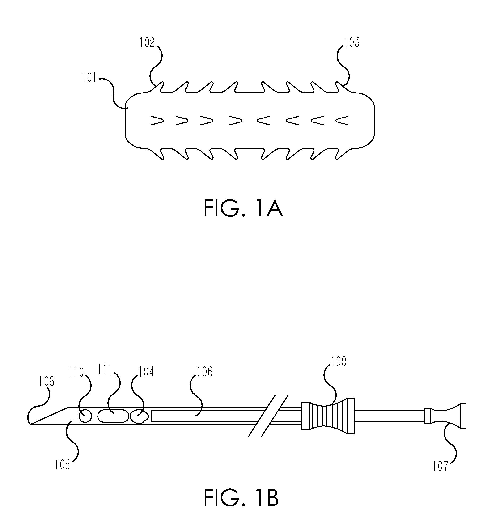
Construction of Fiduciary Markers with Anchoring Moieties and Delivery Needle

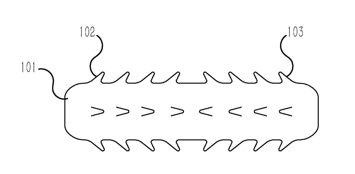
[0089]The starting material for the fiduciary markers was 24 karat gold wire (W.E. Mowrey Company). Large markers (with a body size of approximately 3.2 mm long by 1.1 mm wide) were constructed by cutting 3.2 mm lengths of 17 AWG wire. Small markers (with a body size of approximately 2.1 mm long by 0.65 mm wide) were constructed by cutting 2.1 mm lengths of 22 AWG wire.

[0090]On each marker, four parallel rows of anchoring moieties were made along the long axis of the body, each row spaced at 90 degree intervals circumferentially around the circular body of the marker.

[0091]Anchoring moieties were made by cutting a short distance into the body of the marker with a sharp surgical scalpel at an angle of 30-45 degrees. After cutting into the wire, a slight rotation of the scalpel towards the perpendicular caused the flaps to flare out away from the body of the wire. The resulting flaps of lifted material resemb...

example 2

Use of Fiduciary Markers with Anchoring Moieties to Delineate Tumor Resection Beds

[0096]Between January 2007 and March 2011, the gold fiduciary markers described in Example 1 were tested in a total of 10 patients. Each patient had been diagnosed with a single bladder tumor (focal, T2, NX, M0 transitional cell bladder cancer) and had undergone a primary endoscopic resection of a single tumor from the bladder wall. The patient pool consisted of seven men and three women, mean age 77.4 and 74.7 years, respectively.

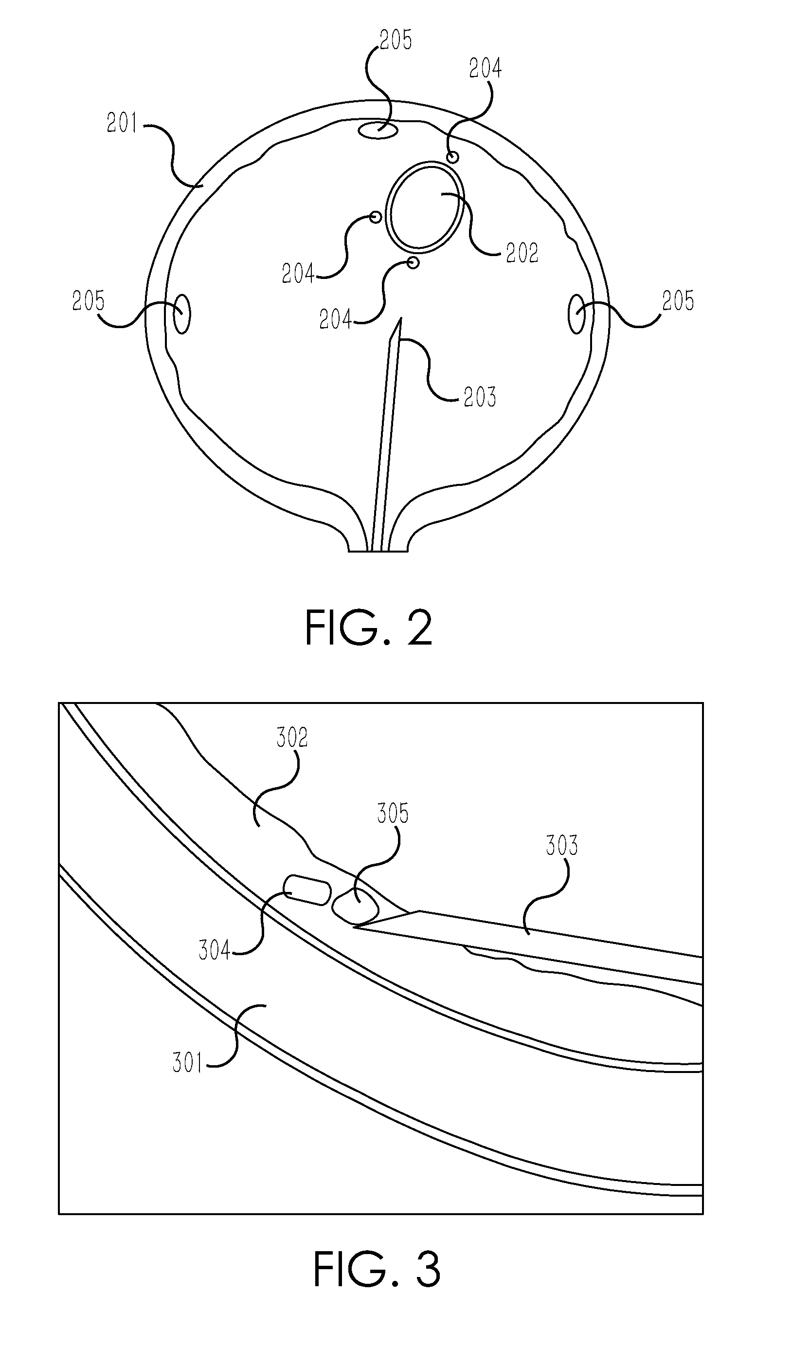
[0097]Fiduciary markers were implanted at the time of bladder tumor repeat resection / fulguration. Using the coaxial delivery needle described in Example 1, conjoined to a standard cystoscope, 3-5 markers were implanted in each patient in a roughly circular pattern outlining the tumor resection bed, for a total of thirty-nine markers placed. Markers were placed in a staggered orientation, such that all markers were visible from both anterior-posterior and lateral radiographic ...

example 3

Delineation of the Whole Bladder Using Fiduciary Markers

[0106]In this Example, the use of the fiduciary markers to delineate the boundaries of the whole bladder is demonstrated. This study was conducted in a male subject having been diagnosed with a 2-3 cm muscle invasive bladder tumor located at the dome of the bladder. The tumor was removed by transurethral resection.

[0107]Three and a half months later, fiduciary markers were implanted in the patient to delineate the tumor resection bed, using the same general method as described in Example 2. The markers had body dimensions of 2.6 mm long by 0.7 mm wide, having four rows of anchoring moieties, made and configured as described in Example 1. Markers were co-injected with following Gelfoam™ plugs, as described in Example 1.

[0108]Four sites were marked with fiduciary markers. A single marker was placed at the right lateral limit of tumor area. A single marker was placed at the left lateral limit of tumor area. A single marker was pla...


PUM


Abstract

The invention relates to the field of radiation oncology, specifically the use of novel radio-opaque fiduciary markers which resist migration within tissues, which may be implanted in the body and imaged during radio-therapy to insure accurate treatment of target regions while avoiding irradiation of non-target regions. In one embodiment, the markers comprise oblong bodies from which a plurality of short tines protrude. Also provided are novel devices for implanting such markers. Additionally, the invention provides methods of delineating tumor resection beds and whole-bladder contours in the radiotherapeutic treatment of bladder cancer. Lastly, the invention encompasses novel methods of delivering fiduciary markers and other implants and materials by needle with sealing aids that increase the retention rate of the delivered markers, implants, or materials.

Description

CROSS-REFERENCE TO RELATED APPLICATIONS[0001]This application is based on and claims the benefit of priority of U.S. Provisional Patent Application Ser. No. 61 / 518,742, filed on May 11, 2011, the contents of which are incorporated by reference in their entirety, and PCT Application Serial Number PCT / US2012 / 037379, filed on May 10, 2012, the contents of which are incorporated by reference in their entirety.STATEMENT REGARDING FEDERALLY SPONSORED RESEARCH OR DEVELOPMENT[0002]This invention was made with United States government support under Grant Number 5-K08-HD069462-02 awarded by the National Institutes of Health. The United States government has certain rights in the invention.REFERENCE TO SEQUENCE LISTING, A TABLE, OR A COMPUTER PROGRAM LISTING COMPACT DISK APPENDIX[0003]Not ApplicableFIELD OF THE INVENTION[0004]The invention relates to the field of radiation oncology, specifically the use of novel radiopaque fiduciary markers which resist migration, devices for implanting them, ...

Claims


Application Information

Patent Timeline
Patent Type & Authority Applications(United States)
IPC IPC(8): A61B19/00A61B6/00A61B6/12A61N5/10A61K49/04
CPCA61B2090/3912A61B2090/3991A61B90/39A61B2090/3966A61P35/00A61B6/12A61B6/481A61B6/485A61K49/04A61N5/1007A61N5/1014
Inventor GARCIA, MAURICE
Owner RGT UNIV OF CALIFORNIA
Why Eureka
Try Eureka