Stereo Vision Encoded Ultrasonic Inspection

a technology of encoded ultrasonic inspection and stereo vision, applied in wave based measurement systems, direction/deviation determining electromagnetic systems, instruments, etc., can solve problems such as difficulty in manual control

Inactive Publication Date: 2014-07-03
AREVA INC
View PDF12 Cites 4 Cited by
  • Summary
  • Abstract
  • Description
  • Claims
  • Application Information

AI Technical Summary

Benefits of technology

[0009]This invention applies optical tracking technology with an NDE inspection system to associate encoded position data with the inspection data. This invention uses optical object tracking technology to provide this encoding and associate the position data with the NDE inspection data. Typically the optical encoding electronics function by tracking the position of known reference markers or targets with multiple cameras simultaneously. The optical tracking system is calibrated such that the physical movement of the reference ta

Problems solved by technology

This is difficult to control manually, but the computer can recognize if the transducer is misaligned and can issue an audible and/or

Method used


Image

  • Stereo Vision Encoded Ultrasonic Inspection
  • Stereo Vision Encoded Ultrasonic Inspection
  • Stereo Vision Encoded Ultrasonic Inspection

Examples


Embodiment Construction

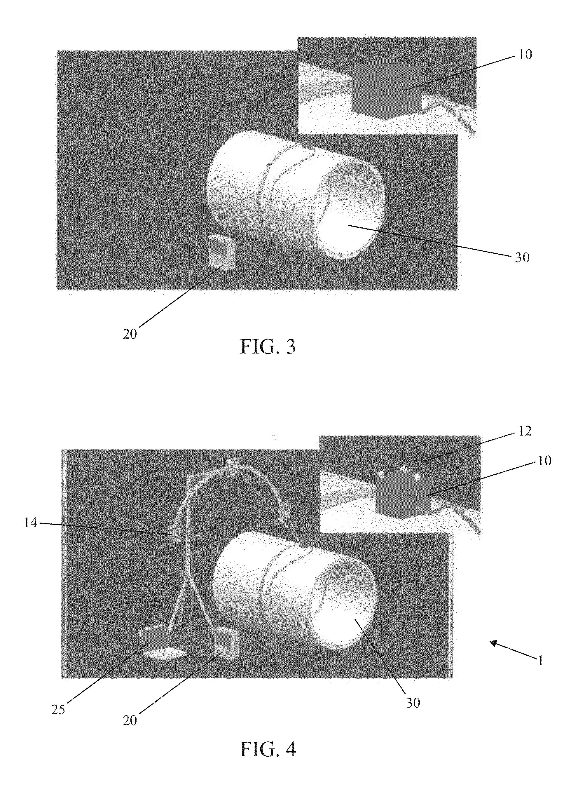
[0018]FIG. 4 shows an example of a preferred inspection system. For a UT examination, an ultrasound transducer 10 is passed over the object 30 being inspected. The transducer 10 emits pulsed ultrasonic waves or electromagnetic waves that are imparted to the object 30. The waves pass into the object 30 and are reflected back by any interface or material anomaly, such as the back wall of the object 30 or from an imperfection within the object such as a crack, pit, eroded area, or a weld inclusion. The transducer 10 receives the reflected waves and sends the received data to connected diagnostic equipment 20, such as an oscilloscope. For UT inspections, these results typically are displayed in the form of a signal with an amplitude representing the intensity of the reflection and the arrival time of the reflection representing the distance (depth) to the reflecting interface. For electromagnetic sensors, the coils generating the electromagnetic waves are sensed for changes in impedance...


PUM


Abstract

This invention applies optical tracking technology with an ultrasound inspection system to associate recorded position data with the inspection data. The reference targets of the optical tracking system can be attached to the inspection assembly to allow fully recorded position information to be associated with the ultrasonic, eddy current, or other nondestructive examination data without substantially impacting the overall envelope of the NDE inspection equipment. Moreover, the optical tracking system can be used to monitor skew or twist of the inspection equipment with respect to the normal rectilinear transducer orientation. The inspection equipment position information is then coupled to the inspection data to provide outputs equivalent to fully encoded multi-axis manipulator automated scans, but with less setup burden and equipment expense.

Description

BACKGROUND OF THE INVENTION[0001]1. Field of the Invention[0002]The present invention relates to an inspection system, and, more particularly, the present invention relates to a system for performing manual inspections while providing fully encoded data.[0003]2. Description of the Related Art[0004]While the present invention may be used in a variety of industries, the environment of nuclear power plant be discussed herein for illustrative purposes. A nuclear power plant relies on the nuclear fuel fission reaction inside a pressure vessel to heat the water, thereby producing steam that drives a turbine that drives a generator that ultimately produces electricity. The steam then passes through condensers to turn it back into water for pumps to ultimately circulate the fluid back into the reactor to be re-heated by the fission reaction and the cycle is repeated. This describes the boiling water reactor or BWR cycle. In pressurized water reactor (PWR) reactors, the hot water passes thro...

Claims


Application Information

Patent Timeline
IPC IPC(8): H04N13/02
CPCH04N13/0242G01N29/265G01N29/043G01N29/226G01N2291/0258G01S5/16G01S3/784H04N13/243
Inventor THIGPEN, BRADLEY A.GLASS, III, SAMUEL WILLIAM
Owner AREVA INC
Why Eureka
Try Eureka