Lubrication systems for bearing assemblies

a technology of bearing assemblies and lubrication systems, which is applied in the direction of water-acting propulsive elements, shafts, vehicles, etc., can solve the problems of high risk of wear, and failure of bearings, and achieve the effect of great accuracy

Active Publication Date: 2014-07-10
GE RENEWABLE TECH WIND BV
View PDF13 Cites 15 Cited by
  • Summary
  • Abstract
  • Description
  • Claims
  • Application Information

AI Technical Summary

Benefits of technology

[0018]The purpose of the monitoring elements is to provide information about the quantity of lubricant injected to, and about the quantity of lubricant extracted from, the bearing during an injection, extraction or combined injection-extraction mode. A central control system may receive this information and act accordingly on the lubrication system. Thanks to the monitoring elements, the central control system may be able to keep a balance between the injected and extracted volumes of lubricant. Moreover, since the central control system may be aware of the initial volume of lubricant inside the bearing (as this parameter is part of the quality control plan of the component at the manufacturing warehouse), it may also be able to inform about possible deviations in regards to under- or over-filling. As a result, failure modes of operation of the respective bearing may be prevented.
[0020]The main advantage of the local pressure measuring instrument is that, apart from controlling the overall volume of lubricant inside the bearing, the lubrication system may also control the distribution of lubricant within the bearing. This may help avoid local lubricant concentrations and, consequently, any sealing failures at the affected points. This is also particularly advantageous in pitch bearing assemblies of wind turbine generators, where specific local lubricant accumulation points may appear due to the topology of the pitch bearing assembly and due to the centrifugal forces subject to the rotation of the wind turbine rotor. These points may be the points at the cross-section of the pitch bearings plane with the rotor plane.
[0021]In some embodiments the monitoring elements may be flow meters and / or manometers. A flow-meter may be connected to a recovery line in order to inform the central control system about possible failures in the recovery line, such as leakage or line breakage. The flow-meter may also deliver information about the used lubricant volume extracted from the bearing. This information may be more reliable than the calculation of the volume of extracted lubricant from the bearing depending on the number of lubrication cycles and the metering of the extraction devices. Accordingly, the central control system may be informed about the volume of lubricant injected thanks to the accurate metering of the injection devices which deliver always the same volume of lubricant at each injection cycle.
[0022]By accurately measuring the volume of lubricant injected and extracted it is possible to predict with great accuracy the amount of lubricant present inside the bearing at any given moment. Therefore, should there be any discrepancy between the expected volume and the measured volume, it is possible to take early corrective measures, such as provide extra injection cycles or extra extraction cycles.
[0024]In some embodiments, the injection devices may be arranged in series in the injection circuit. Accordingly, the extraction devices may be arranged in series in the extraction circuit, respectively. In these embodiments, the lubrication system may further comprise a second three-way valve coupled to the pump. The first three-way valve may be coupled to the first injection device and to the first extraction device in the series, respectively, and the second three-way valve may be coupled to the last injection device and to the last extraction device in the series, respectively. The advantage of having two 3-way valves in a circuit is that a more homogenous pressure may be achieved throughout the lubrication circuit during a lubrication cycle.
[0027]In another aspect, a pitch bearing assembly for a wind turbine generator is disclosed. The pitch bearing assembly may comprise three bearings and a lubrication system according to any of the embodiments described above. The advantage of having a dissociated lubrication system in a pitch bearing assembly is that the volume and distribution of lubricant in the respective bearings may be better controlled, thus increasing the durability of the bearings and reducing the maintenance and repair costs. As a result, the service life of the pitch bearings may be extended which may significantly reduce the maintenance costs of the overall wind turbine generator.

Problems solved by technology

Although rolling bearings often work well in non-ideal conditions, sometimes minor problems may cause bearings to fail quickly and unpredictably.
However, after a significant operating time, the volume of lubricant inside the bearing may divert from the ideal percentage.
Consequently, the friction at the load transmission areas may increase and so does the risk of wear initiation.
Furthermore, the increased friction increases in turn the temperature of the remaining lubricant.
Thus, the lubricant may suffer accelerated aging damage which may affect its performance.
In extreme cases, damaged additives, soaps and oil may even accelerate the initiation of fatigue signs inside the bearing.
On the other hand, bearings working with a level of lubricant above the ideal level may be exposed to local excess pressure inside the component due to the combined effects of accumulation of lubricant close to the bearing inlets and rolling motion of the balls or rollers in the same area.
An overpressure inside a bearing may lead to failure of the sealing means.
For example, in case of 4 points contact slew bearings, rubber seals may pop out of their housing and leave the component exposed to lubricant leakage and external agent contamination.
This last consequence may be critical for the service life of bearings since it may generally lead to indentation effects or corrosion of the raceways in case water or solid contaminants enter inside the bearing.
Wind turbine generators employ large bearing assemblies, such as the main, pitch and yaw bearing assemblies that are subject to particularly heavy loads.
Furthermore, the orientation of the bearings, with respect to, for example, the wind turbine rotor blade, may lead to high concentrations of lubricant in certain areas during periods of low or no wind.
For example, in a pitch bearing assembly of a wind turbine generator, certain zones of the bearings may suffer from lubricant concentration and the bearings may potentially be affected by an internal overpressure at these zones.
A combination of gravity and centrifugal forces may cause concentration of lubricant and overpressure in the affected zones.
However, although the existing lubrication control systems may be able to monitor precisely the amount of injected lubricant, the amount of remaining lubricant inside the bearing remains out of their scope.
Furthermore, the distribution of lubricant inside the bearing remains unknown.

Method used


Image

  • Lubrication systems for bearing assemblies
  • Lubrication systems for bearing assemblies
  • Lubrication systems for bearing assemblies

Examples


Embodiment Construction

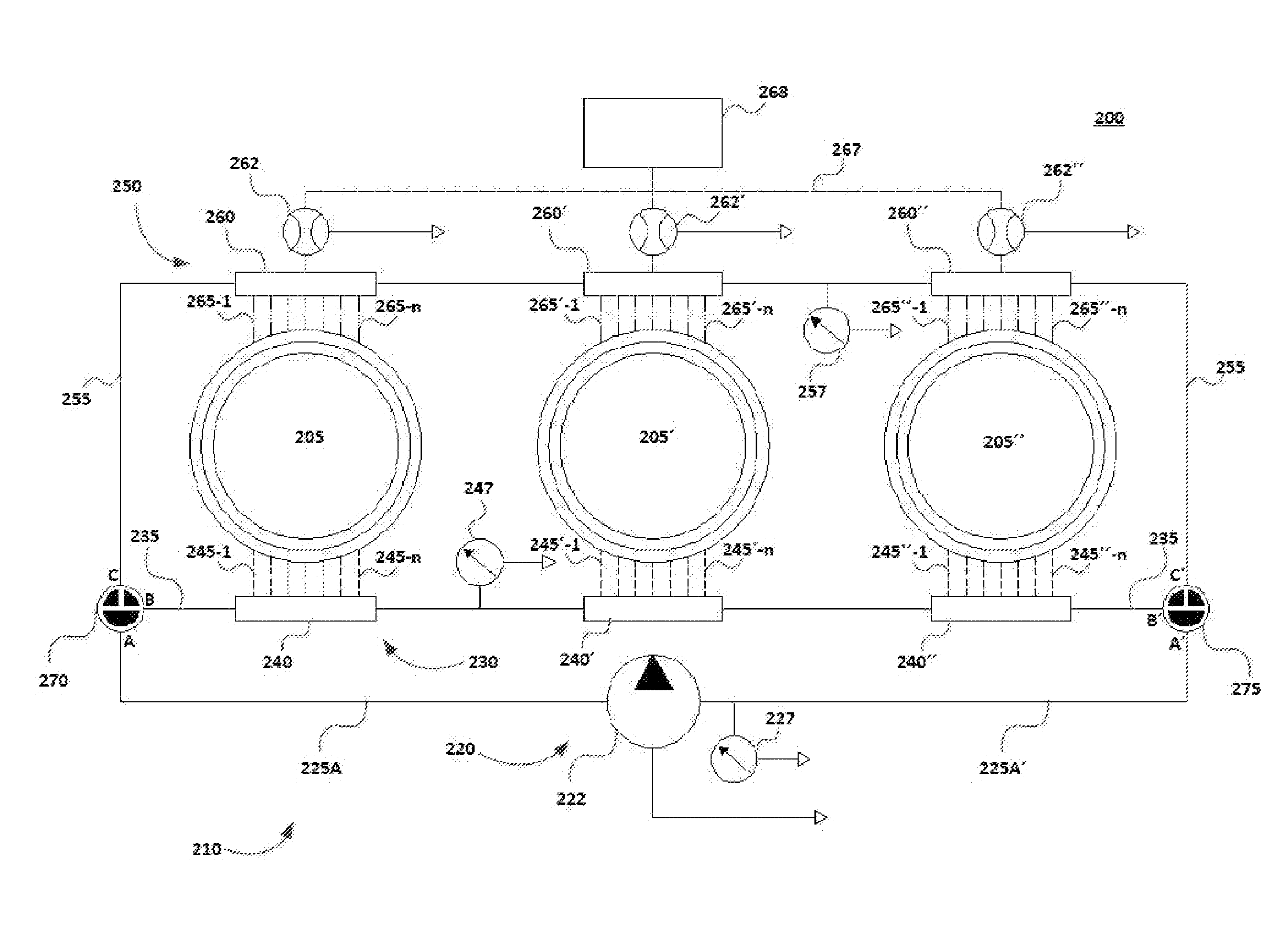
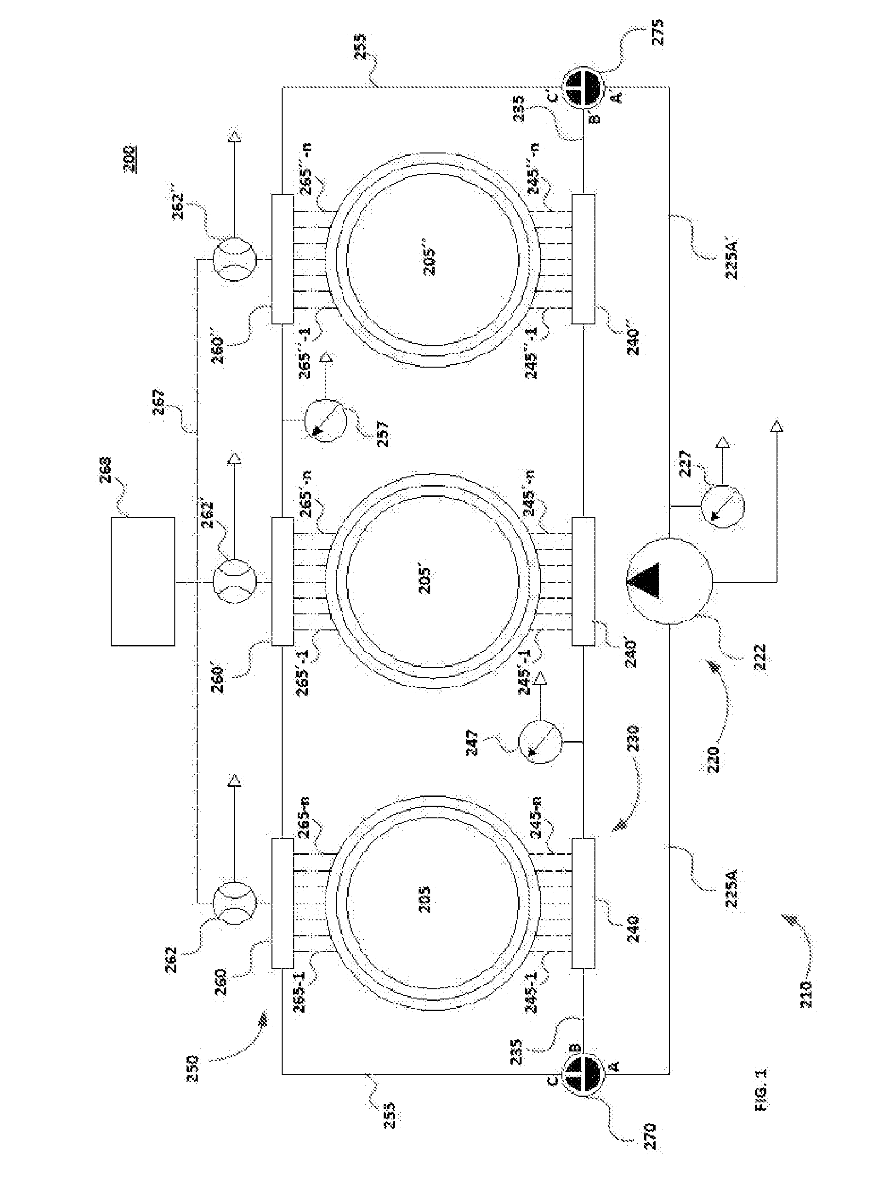
[0035]FIG. 1 is a block diagram of a bearing assembly according to an embodiment. Bearing assembly 200 may include three bearings 205, 205′ and 205″ and lubrication system 210. Lubrication system 210 may include pump circuit 220, injection circuit 230, extraction circuit 250 and 3-way T-shaped valves 270, 275. Each of the 3-way valves 270, 275 may have a first port A, A′ coupled to the pump circuit 220, a second port B, B′ coupled to the injection circuit 230 and a third port C, C′ coupled to the extraction circuit 250.

[0036]Pump circuit 220 may include pump 222 and main line 225. Main line 225 may have two branches, 225A and 225A′, one coupled to first port A of valve 270 and the other coupled to first port A′ of valve 275. Each of the two branches 225A and 225A′ may be split in an injection branch 235 and an extraction branch 255. The main line 225, and consequently, the injection branch 235 and the extraction branch 255, are used to supply pressure to the injection circuit 230 an...


PUM


Abstract

A lubrication system is disclosed for a bearing assembly, the bearing assembly having at least one bearing. The lubrication system may comprise a pump circuit, an injection circuit, an extraction circuit and at least one three-way valve. The pump circuit may comprise at least a pump. The injection circuit may provide lubricant to the bearing during an injection mode of operation. The extraction circuit may extract lubricant from the bearing during an extraction mode of operation. A flow combination topology of the first three-way valve may allow operation of the lubrication system in the injection mode or in the extraction mode or in both modes simultaneously.

Description

[0001]This application claims the benefit of European Patent Application no. 13382004.3 filed on Jan. 10, 2013 and U.S. Provisional Patent Application Ser. No 61 / 776,552 filed on Mar. 11, 2013, the disclosures of which are hereby incorporated by reference in their entirety for all purposes.[0002]The present invention relates to bearings and more specifically to lubrication systems for bearing assemblies.BACKGROUND ART[0003]Large bearings, and particularly large rolling bearings, are typically submitted to heavy loads. Such heavy loads may be imposed to these bearings either in stress conditions or at rest. Although each bearing may be appropriately selected and dimensioned for a particular heavy load application, proper lubrication may generally be regarded as an important factor for its overall performance during the bearing's estimated service life.[0004]Although rolling bearings often work well in non-ideal conditions, sometimes minor problems may cause bearings to fail quickly a...

Claims


Application Information

Patent Timeline
Patent Type & Authority Applications(United States)
IPC IPC(8): F16N7/38F03D11/00
CPCF03D11/0008F16N7/385F16C33/6674F16C2360/31F03D80/70Y02E10/72F16N7/40F16N29/00F16N2250/04F16N2250/40
Inventor PASQUET, PIERRE
Owner GE RENEWABLE TECH WIND BV
Why Eureka
Try Eureka