In-Pixel Ultrasonic Touch Sensor for Display Applications

a touch sensor and ultrasonic technology, applied in the field of image display technology, can solve the problems of light absorption loss, complexity, and additional cost, and achieve the effect of removing the attachment of the sensor to the display and adding the cost of the touch sensor substra

Inactive Publication Date: 2014-07-17
SHARP KK
View PDF3 Cites 59 Cited by
  • Summary
  • Abstract
  • Description
  • Claims
  • Application Information

AI Technical Summary

Benefits of technology

[0015]Ultrasonic sensor technology has several advantages over existing technologies for touch screen applications. The object used to interact with the touch sensor can be essentially anything that absorbs ultrasonic energy. Unlike current touch screen technology using capacitive sensing, the ultrasonic sensor can detect a metal stylus, a calligraphy brush, a pencil point, or a gloved finger. The touch sensor is integrated in the display, so that the added cost of a touch sensor substrate, and the attachment of the sensor to the display is removed. The sensing is enabled using existing display backplane circuits so that the only additional processing required is for the addition of the piezoelectric material in the pixel storage capacitor. Because the sensors are integrated in each display pixel, touch resolution is inherently that of the display, and touch location is directly mapped to pixel location.

Problems solved by technology

Both of these technologies are fabricated independently of the display and are attached to the front of the display causing additional cost, complexity, and some loss of light due to absorption.

Method used


Image

  • In-Pixel Ultrasonic Touch Sensor for Display Applications
  • In-Pixel Ultrasonic Touch Sensor for Display Applications
  • In-Pixel Ultrasonic Touch Sensor for Display Applications

Examples


Embodiment Construction

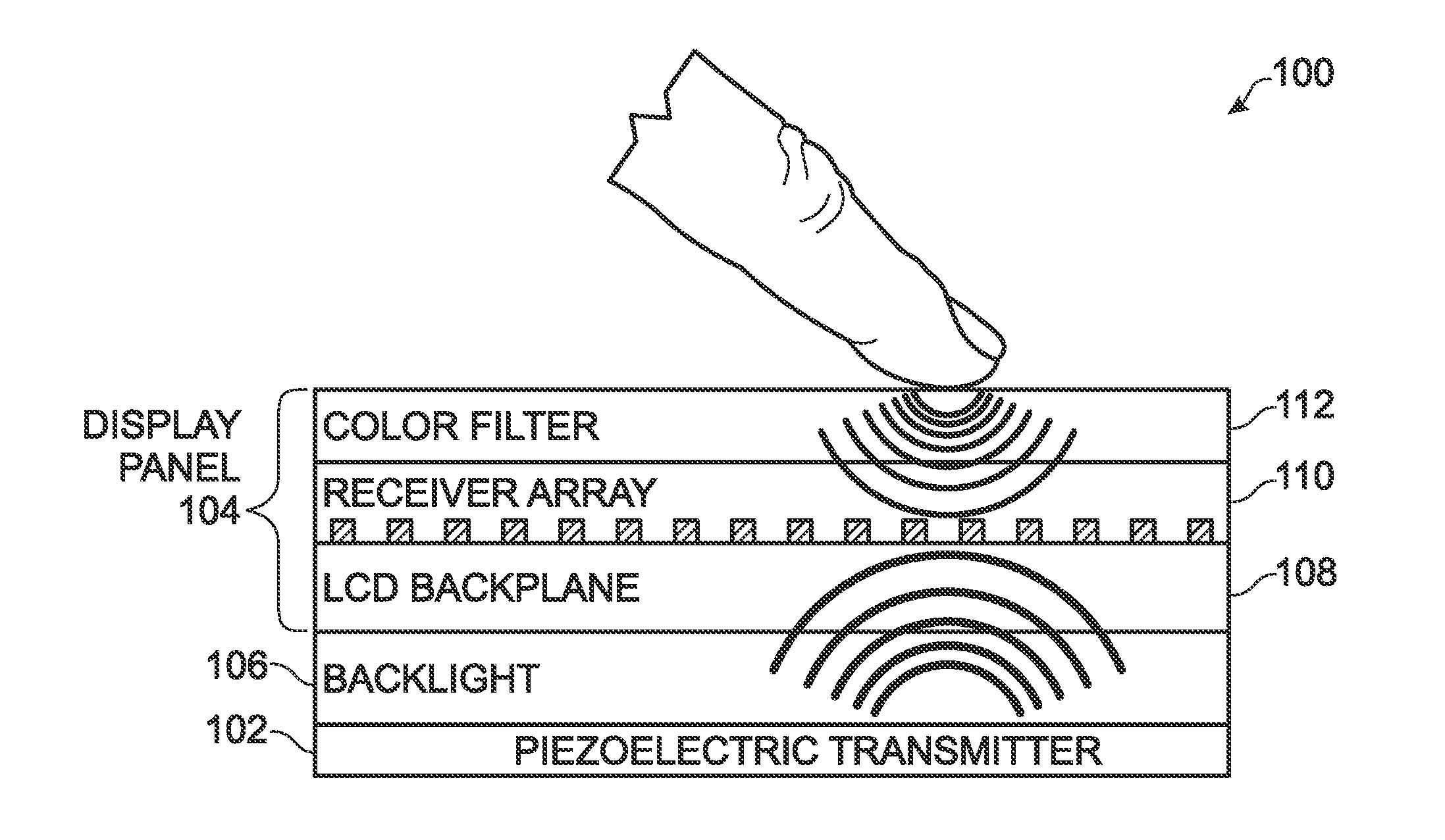
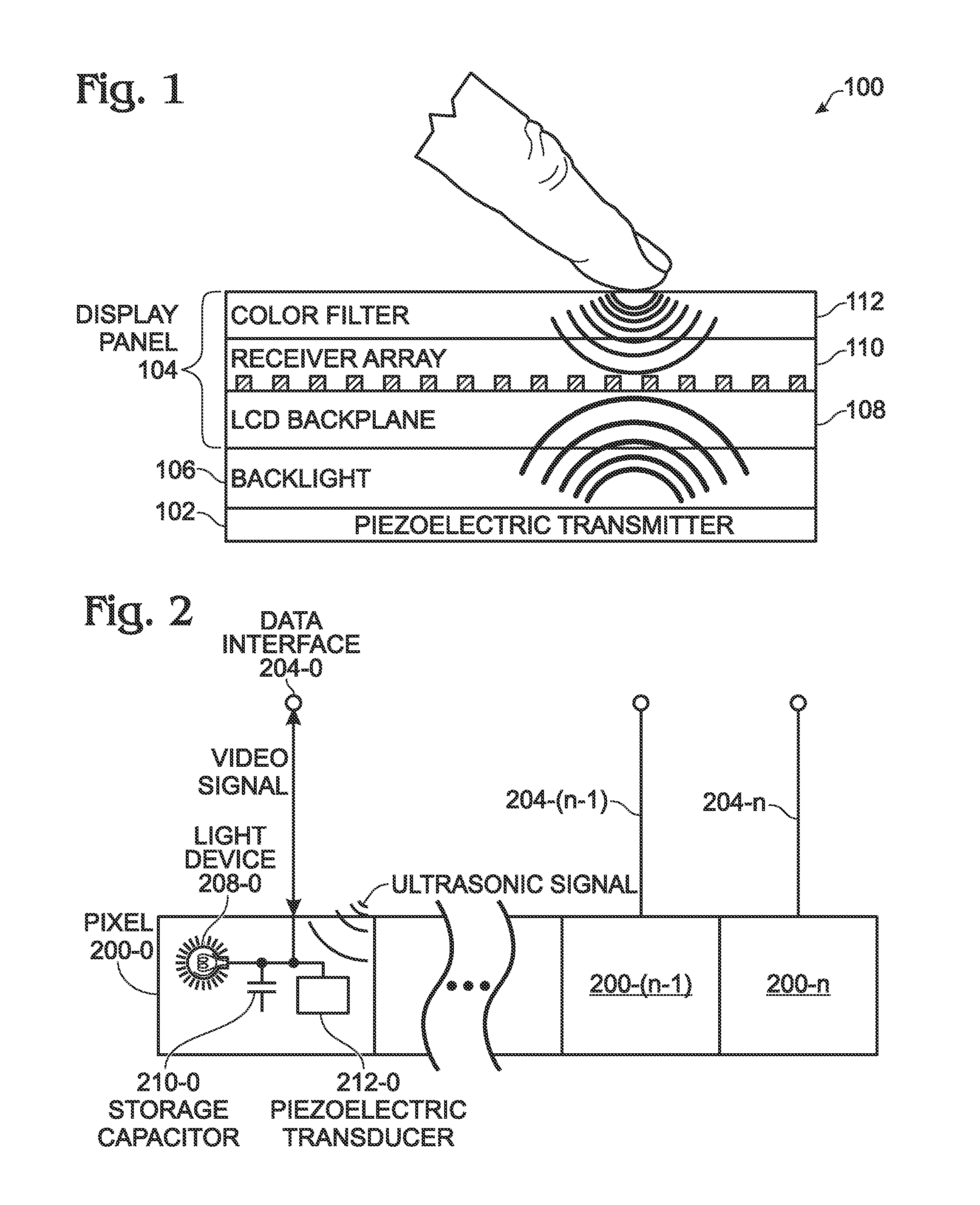
[0042]FIG. 1 is a schematic drawing depicting a planar piezoelectric transducer transmitting an ultrasonic pulse through an exemplary liquid crystal display (LCD) display. The display 100 consists of an ultrasonic transmitter 102 and a display panel 104. In this example, the display 100 includes a backlight 106, and the display panel 104 includes an LCD backplane 108 that also incorporates an array of piezoelectric receivers 110 and a color filter layer 112. As explained in more detail below, each receiver array element is incorporated into a corresponding pixel. The ultrasonic pulse is reflected from the front surface of the display because of the large difference in density between air and the color filter glass. However, if an object with a density greater than air, such as a fingertip, stylus, or a calligraphy brush touches the display front surface, more ultrasonic energy is absorbed by the object and the reflected ultrasonic energy is weaker. Thus, the piezoelectric response a...


PUM


Abstract

A video display is provided with a planar piezoelectric transmitter to transmit ultrasound signals, and a display panel including a plurality of pixels. Each pixel has a data interface to accept a video signal with a variable voltage associated with a range of light intensity values, and to supply a touch signal with a variable voltage derived from a range of reflected ultrasound signal energies. Each pixel is made up of a light device to supply light with an intensity responsive to the video signal voltage, and a storage capacitor to maintain a video signal voltage between refresh cycles. A piezoelectric transducer accepts a reflected ultrasound signal energy and maintains a touch signal voltage between refresh cycles. In one aspect, the storage capacitor and the piezoelectric transducer are the same device. The light device may be a liquid crystal (LC) layer or a light emitting diode.

Description

BACKGROUND OF THE INVENTION[0001]1. Field of the Invention[0002]This invention generally relates to image display technology and, more particularly, to ultrasonic wavelength touch sensors that are fabricated as an integral part of the display pixels.[0003]2. Description of the Related Art[0004]There are many available touch sensor technologies, but the market is currently dominated by two technologies. Low cost systems that do not need multi-touch capability often use resistive touch, which measures the resistance of a conductive network that is deformed by touch creating a connection between X and Y bus lines. The most commonly used multi-touch sensing technology, which is referred to as projected capacitive, measures the capacitance between each pair of electrodes in a cross point array. The capacitance of a finger close to the sensor changes the mutual capacitance at that point in the array. Both of these technologies are fabricated independently of the display and are attached t...

Claims


Application Information

Patent Timeline
Patent Type & Authority Applications(United States)
IPC IPC(8): G06F3/044
CPCG06F3/044G06F3/0412G06F3/043
Inventor SCHUELE, PAUL J.AFENTAKIS, THEMISTOKLESHARTZELL, JOHN W.
Owner SHARP KK
Why Eureka
Try Eureka