Electronic device

a technology of electronic devices and power storage devices, applied in the field of electronic devices, can solve the problems of reducing volume efficiency, increasing volume, and difficulty in providing power storage devices indoors, and achieve the effects of high capacity, long life and high capacity

Inactive Publication Date: 2014-07-17
SEMICON ENERGY LAB CO LTD
View PDF11 Cites 11 Cited by
  • Summary
  • Abstract
  • Description
  • Claims
  • Application Information

AI Technical Summary

Benefits of technology

[0015]According to one embodiment of the present invention, a power storage device with high capacity can be provided. A small-sized power storage device with high capacity which can be provided indoors can be provided. A power storage device having a long lifetime can be provided. The reliability of a power storage device can be improved.
[0016]When power storage devices of one embodiment of the present invention are widely used, as the number of houses which include the power storage devices of one embodiment of the present invention indoors is increased, burdens of a power plant in a region where the houses are located are reduced, which can contribute to an effective use and a stable supply of power. Further, according to one embodiment of the present invention, the power storage device is charged in the night time when the use amount of power is small, and is used in the day time when the use amount of power is large; thus, power can be efficiently charged and used. Furthermore, since the power storage device is used in the day time when the usage charges of a commercial power source are high, the electricity charges are low and an economic merit can be obtained.

Problems solved by technology

Furthermore, when the lifetime of the power storage devices is increased, the volume efficiency is decreased, leading to an increase in the volume.
When the volume of the power storage devices is increased, it is difficult to provide the power storage device indoors; thus, the power storage device needs to be provided outdoors.
However, when the power storage device is provided outdoors, the power storage device is exposed to rain or the like and thus degraded by moisture.
Further, in the case where the power storage device is provided outdoors, when the outside air is at a low temperature (e.g., minus temperature range), the power storage device is significantly degraded, so that the lifetime of the power storage device is decreased.
In order to suppress degradation of the power storage device, regular maintenance of the power storage device is required; thus, in addition to cost for purchasing the power storage device, maintenance cost and the like are further needed.
Consequently, burdens of cost of a power storage device are large for an individual.
Even in the case where a large power storage device can be provided outside the individual house, it is difficult to ensure a carrying path for settlement.

Method used


Image

  • Electronic device
  • Electronic device
  • Electronic device

Examples


embodiment 1

[0030]In this embodiment, a power storage device of one embodiment of the present invention will be described with reference to FIGS. 1A and 1B.

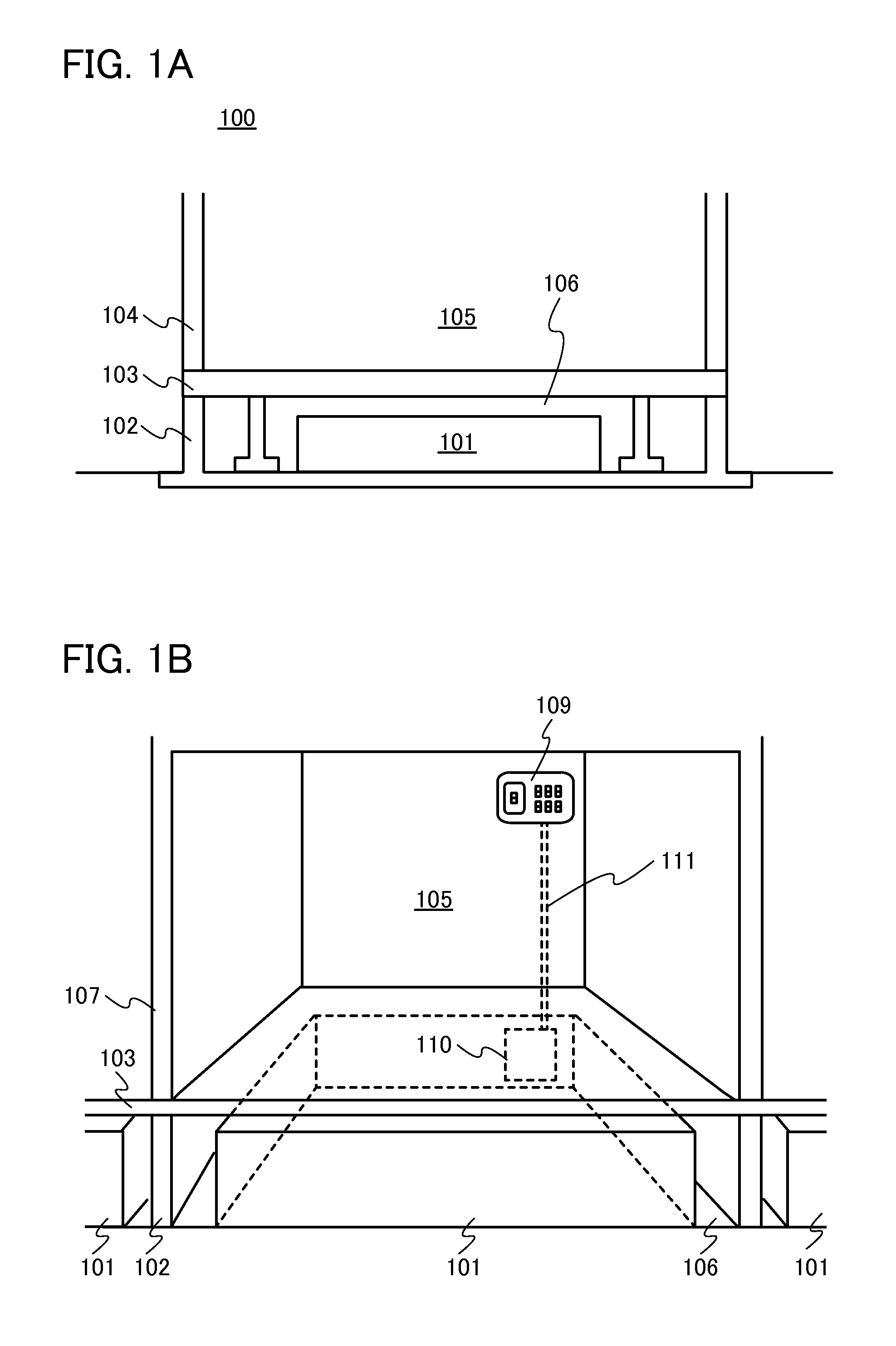
[0031]A building 100 illustrated in FIG. 1A includes a base 102, a floor 103, an exterior wall 104, a space 105, and an underfloor space 106. A power storage device 101 (also referred to as an electronic device) of one embodiment of the present invention is stored in the underfloor space 106, which is surrounded by the base 102 and the floor 103 of the building 100.

[0032]Further, as illustrated in FIG. 1B, the underfloor space 106 is surrounded by the base 102 in the building 100. Further, the inside of the building 100 is partitioned by an interior wall 107. The power storage device 101 is stored in the underfloor space 106. In the case where there are a plurality of underfloor spaces 106 surrounded by the base 102, the power storage device 101 can be stored in each of the underfloor spaces 106.

[0033]The power storage device 101 of one embo...

embodiment 2

[0092]In this embodiment, the battery cell described in Embodiment 1 and a manufacturing method thereof are described with reference to FIGS. 5A and 5B and FIGS. 6A and 6B.

[0093]First, a positive electrode of a battery cell is described with reference to FIGS. 5A and 5B.

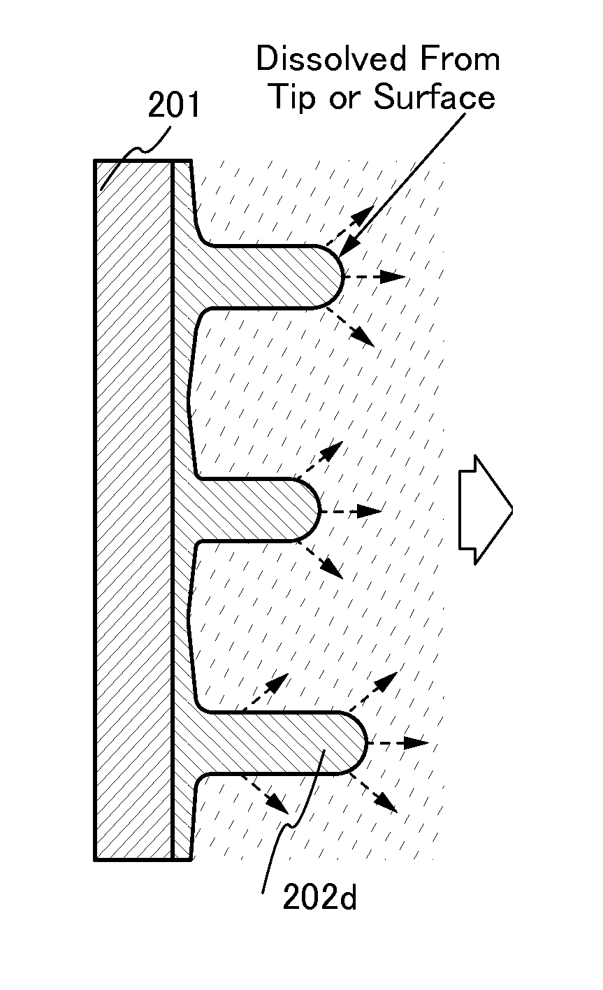
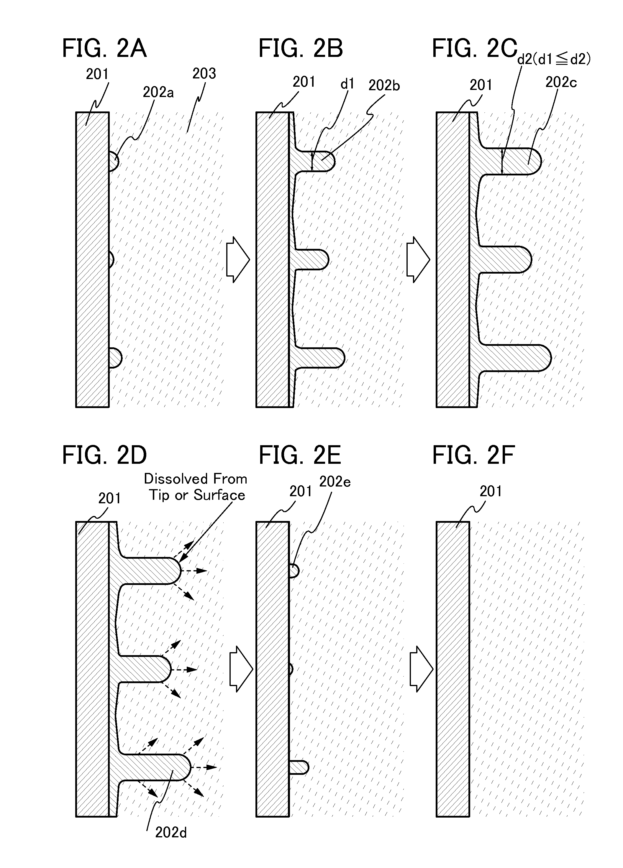
[0094]A positive electrode 400 includes a positive electrode current collector 401 and a positive electrode active material layer 402 formed over the positive electrode current collector 401 by a coating method, a CVD method, a sputtering method, or the like, for example. Although an example of providing the positive electrode active material layer 402 on both surfaces of the positive electrode current collector 401 with a sheet shape (or a strip-like shape) is illustrated in FIG. 5A, one embodiment of the present invention is not limited to this example. The positive electrode active material layer 402 may be provided on one of the surfaces of the positive electrode current collector 401. Further, although the posit...

embodiment 3

[0176]In this embodiment, an example of a power storage system 500 using a power storage device of the present invention is described with reference to FIG. 8.

[0177]As illustrated in FIG. 8, the power storage device 101 of one embodiment of the present invention is provided in the underfloor space 106 of the building 100. For example, the power storage device 101 of one embodiment of the present invention performs charging using an AC / DC converter in the night time and discharging using a DC / AC converter in the day time.

[0178]The power storage device 101 is electrically connected to a distribution board 503, a power storage distribution board 504, and a power storage controller 505.

[0179]Power is supplied to the distribution board 503 from the power storage device 101 and a commercial power source 501. Further, the commercial power source 501 supplies power to the distribution board 503 through a mounting portion 510 of a service wire. Moreover, the distribution board 503 is electri...


PUM

PropertyMeasurementUnit
thicknessaaaaaaaaaa
interlayer distanceaaaaaaaaaa

Abstract

To provide an electronic device having high capacity and high reliability. To provide an electronic device with a small size which can be provided indoors even when it has high capacity. The electronic device includes a plurality of battery cells connected in series. The plurality of battery cells each include a first electrode, a second electrode, and an electrolytic solution between the first electrode and the second electrode. A reaction product, which grows from a surface of the first electrode when a current is supplied between the first electrode and the second electrode, is dissolved from its tip or surface by applying a signal to supply a current reverse to the current. The electronic device is stored in an underfloor space surrounded by a base and a floor of a building.

Description

BACKGROUND OF THE INVENTION[0001]1. Field of the Invention[0002]The present invention relates to an electronic device and a manufacturing method thereof. In addition, the present invention relates to a system having a function of reducing the degree of degradation of an electronic device.[0003]Note that an electronic device in this specification and the like generally means a device that can operate by utilizing a battery (also referred to as a power storage device), a conductive layer, a resistor, a capacitor, and the like.[0004]2. Description of the Related Art[0005]In recent years, a variety of power storage devices such as battery cells including lithium-ion secondary batteries and the like, lithium ion capacitors, and air cells have been actively developed. In particular, demand for lithium-ion secondary batteries with high output and high energy density has rapidly grown with the development of the semiconductor industry, for electrical devices, for example, portable informati...

Claims


Application Information

Patent Timeline
Patent Type & Authority Applications(United States)
IPC IPC(8): H01M10/44H01M10/42
CPCH01M10/4207H01M10/441H01M10/052H01M10/4242H01M2220/30Y02E60/10
Inventor YAMAZAKI, SHUNPEI
Owner SEMICON ENERGY LAB CO LTD
Why Eureka
Try Eureka