Device for stable subsea electric power transmission to run subsea high speed motors or other subsea loads

a high-speed motor and electric power technology, applied in the direction of sea energy generation, ac network voltage adjustment, ac network circuit arrangement, etc., can solve the problems of limited oil quantity, no subsea installation and operation, and the disadvantage of long step-out of transmission cables per motor

Active Publication Date: 2014-07-24
AKER SOLUTIONS AS
View PDF5 Cites 24 Cited by
  • Summary
  • Abstract
  • Description
  • Claims
  • Application Information

AI Technical Summary

Benefits of technology

[0040]From the above equation can be concluded that the Ferranti effect of a long line can be compensated by a suitable reduction of the electri...

Problems solved by technology

Whereas exploitation of fossil fuels was previously focused on onshore fields, the limited amount of oil started serious efforts to find and exploit offshore gas and oil fields.
The disadvantage for subsea compressors per 2010 is that none has been installed and operated subsea, i.e. the technology is not proven.
Subsea pressure boosting requiring a significant subsea step out length is a very recent technology using modern equipment and facing problems that are not met or is irrelevant elsewhere.
This solution with one transmission cable per motor has the disadvantage of becoming expensive for long step-out; say more than 50 km, due to high cable cost.
A serious technical obstacle against this solution is that at a certain subsea step-out length, the transmission of electric power from a near end power source to a far end distant motor is not feasible because the transmission system will become electrically unstable and inoperable due to the Ferranti effect that later will be described.
These are expensive VSDs which are not proven ...

Method used


Image

  • Device for stable subsea electric power transmission to run subsea high speed motors or other subsea loads
  • Device for stable subsea electric power transmission to run subsea high speed motors or other subsea loads
  • Device for stable subsea electric power transmission to run subsea high speed motors or other subsea loads

Examples


Embodiment Construction

with Frequency Step-Up to Run AC Motors

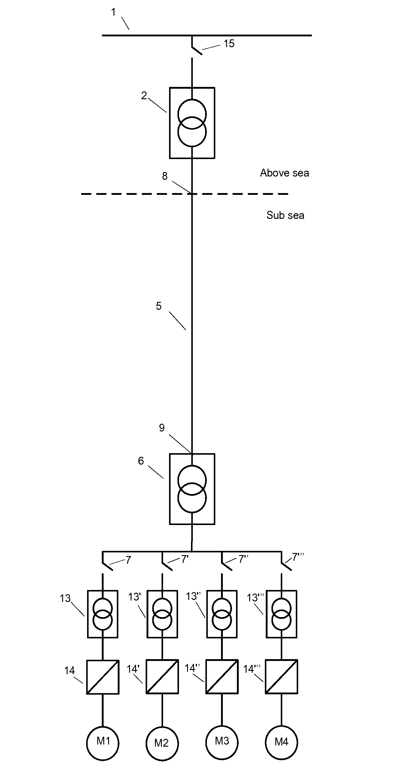
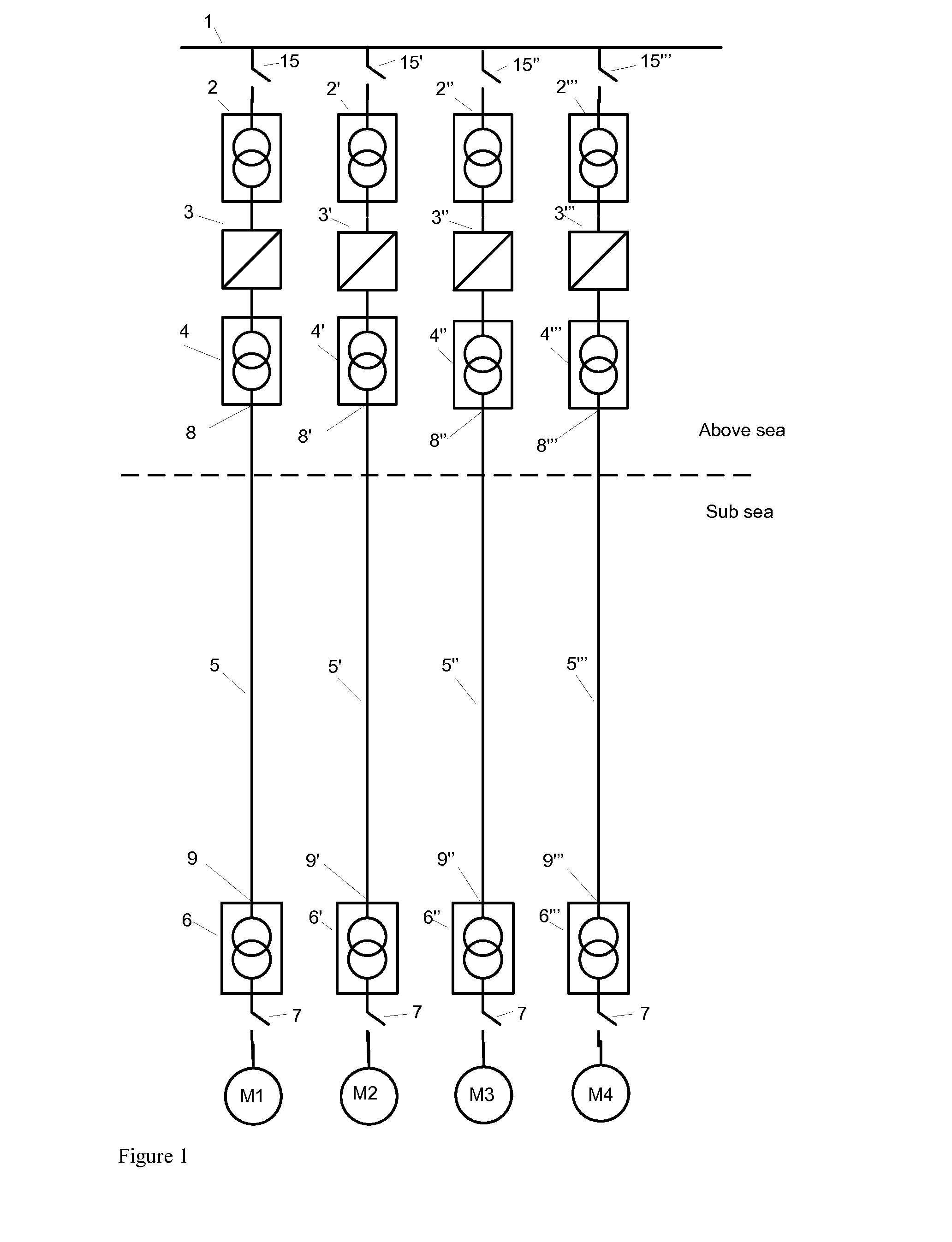
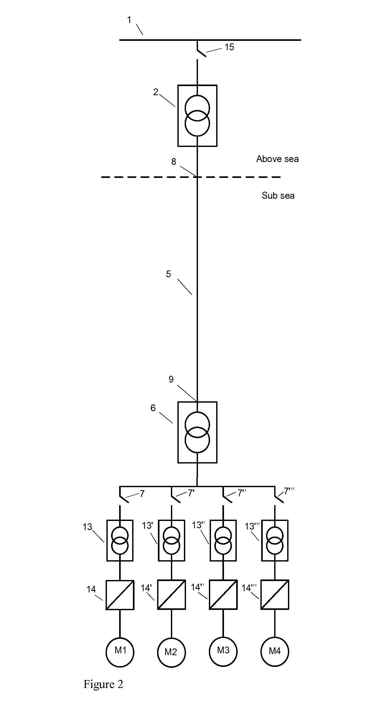
[0068]An embodiment of the invention, the Fourth Solution is shown in FIGS. 4 and 5. The main feature of the embodiment is introduction of a subsea frequency step up or step down device, in the illustrated embodiment a frequency step-up device (FSD) located subsea at the far end of the transmission cable and at a short distance to the motors that runs the compressors and pumps. Short distance means in this context near enough to keep acceptable the ohmic resistance drop and thereby power loss between the generator / FSD and the motors, and it also means short enough to avoid problems caused by Ferranti effect and instability. It is important to note that the subsea FSDs are not directly controlling the frequency to suit the operational speed of motors by having a local control system that adjusts the speed according to needs. The variation of speed according to steady state production need, start and stop and ramping speed down and up, is done by...


PUM


Abstract

The invention provides a device for operative connection between a subsea step out cable far end and subsea loads such as pumps, compressors and control systems, distinctive in that the device is a rotating frequency stepper device, more specifically a rotating step up or step down device, and it comprises: a motor and a generator operatively connected so that the motor drives the generator, at least one gas and/or liquid filled vessel into which at least one of the motor and generator are arranged, and the step out length is long, which means long enough to cause problems due to the Ferranti effect at frequency and power levels feasible for subsea pump and compressor motors, and where the device via the step out cable receives input electrical power at a low enough frequency to have stable transmission and the device, operatively connected to the subsea motor, delivers an output electrical frequency, amperage and voltage feasible for operation of the connected motors. System for pressure boosting of hydrocarbon fluid or other fluid subsea, comprising the device.

Description

FIELD OF THE INVENTION[0001]The present invention relates to equipment for subsea production of petroleum, particularly equipment located far away from dry topside or onshore locations. More specifically, the invention relates to equipment for electric power transmission to subsea loads that can be located far away from surface platforms or shore and require high power transmission. Said loads are typically motors for pumps and compressors which require control of rotational speed by control of the electric frequency.[0002]The invention come to grips with the problems caused by the Ferranti effect and the skin effect, thereby opening up for longer subsea step out lengths than previously achievable.BACKGROUND OF THE INVENTION AND PRIOR ART[0003]Over the last decades global energy consumption has increased exponentially and no end can be seen for the increased demand. Whereas exploitation of fossil fuels was previously focused on onshore fields, the limited amount of oil started serio...

Claims


Application Information

Patent Timeline
IPC IPC(8): H02J3/22H02M5/32
CPCH02M5/32H02J3/22H02P5/74Y02E10/30
Inventor STINESSEN, KJELL OLAV
Owner AKER SOLUTIONS AS
Why Eureka
Try Eureka