Filtering of a time-dependent pressure signal

a filtering and pressure signal technology, applied in the field of processing a time-dependent pressure signal, can solve the problems of generating an average, unable to provide information on the shape of the heart pulse, and unable to provide data on the magnitude or timing of individual heart pulses, etc., to achieve the effect of improving processing or memory capacity and being simple to implemen

Active Publication Date: 2014-08-21
GAMBRO LUNDIA AB
View PDF10 Cites 17 Cited by
  • Summary
  • Abstract
  • Description
  • Claims
  • Application Information

AI Technical Summary

Benefits of technology

[0010]Another objective is to provide such a technique that is simple to implement in a fluid containing system.
[0011]A further objective is to provide a filtering technique with an improved usage of processing or memory capacity.

Problems solved by technology

It is a challenging task to extract the information component by removing the disturbance component.
The latter technique is only able to generate an estimate of the average heart pulse magnitude, and provides neither information on the shape of the heart pulse, nor data on the magnitude or timing of individual heart pulses.
However, existing solutions often require extensive memory and processing usage for processing the pressure signals, and they may also be unable to provide instantaneous information about the physiological pulses, such as magnitude, shape and timing.
These pump pressure profiles may be difficult to obtain, may increase the complexity of implementation, and may generate unreliable results unless care is taken when measuring / calculating the pump pressure profiles.
In comparison to prior art techniques, the inventive filtering also obviates the need to pre-record or pre-calculate reference profiles, the need to store these reference profiles, and the complexity of using such stored reference profiles for filtering of the pressure signal.

Method used


Image

  • Filtering of a time-dependent pressure signal
  • Filtering of a time-dependent pressure signal
  • Filtering of a time-dependent pressure signal

Examples


example i

Reference Value Based on a Corresponding Cycle-Synchronized Sample of the Immediately Preceding Pulse Cycle

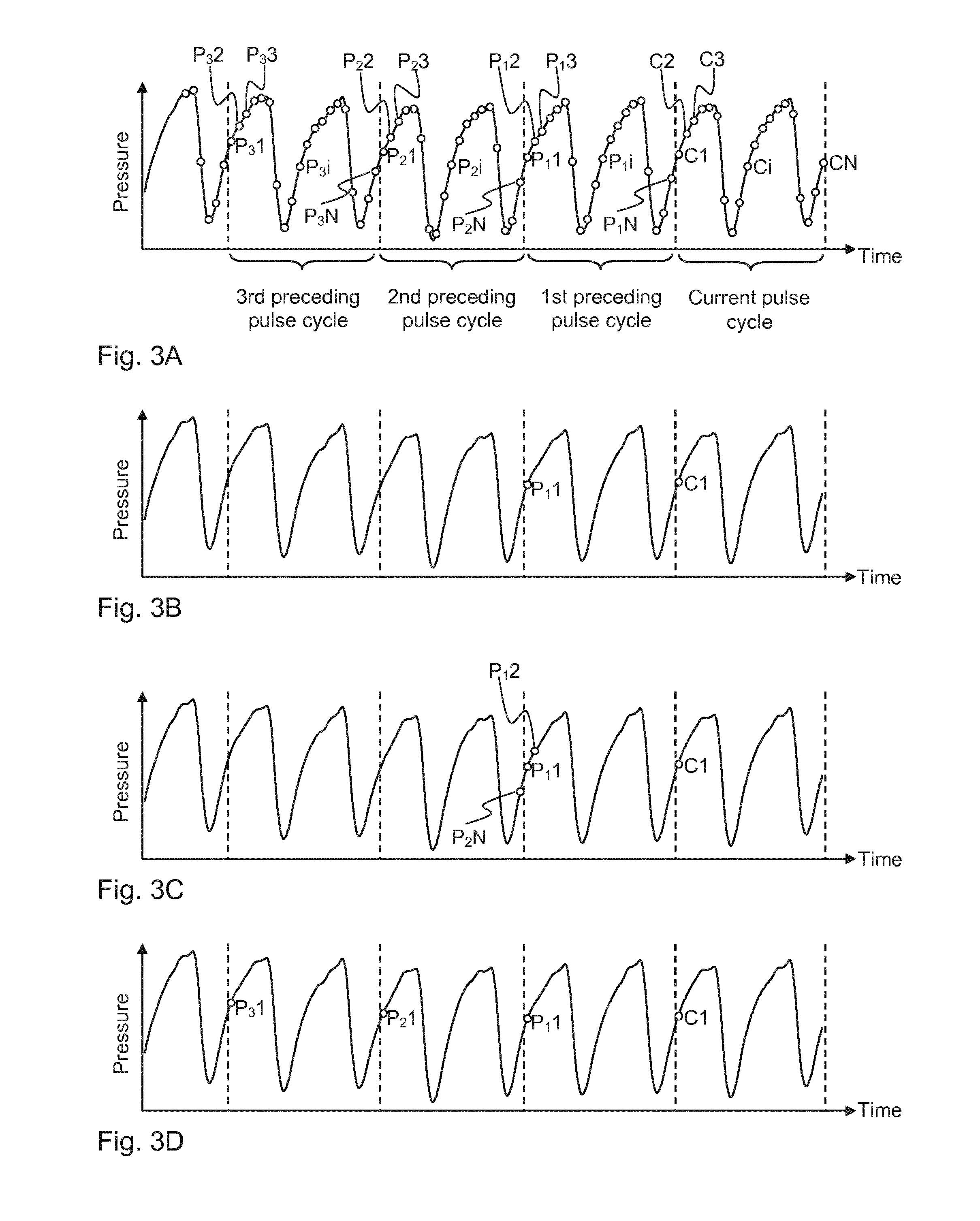
[0072]FIG. 3B illustrates a first example where a reference value is obtained based on a corresponding cycle-synchronized sample of the immediately preceding pulse cycle. FIG. 3B shows a current data sample C1 from a first position in the current pulse cycle and one preceding cycle-synchronized data sample P11 from a first position in the first preceding pulse cycle corresponding to the relative location of the current data sample in the current pulse cycle. In the example with a peristaltic pump, the cycle-synchronized data sample P11 has been obtained at an instance in time corresponding to one full rotation earlier of the rotor, i.e. 360 degrees earlier.

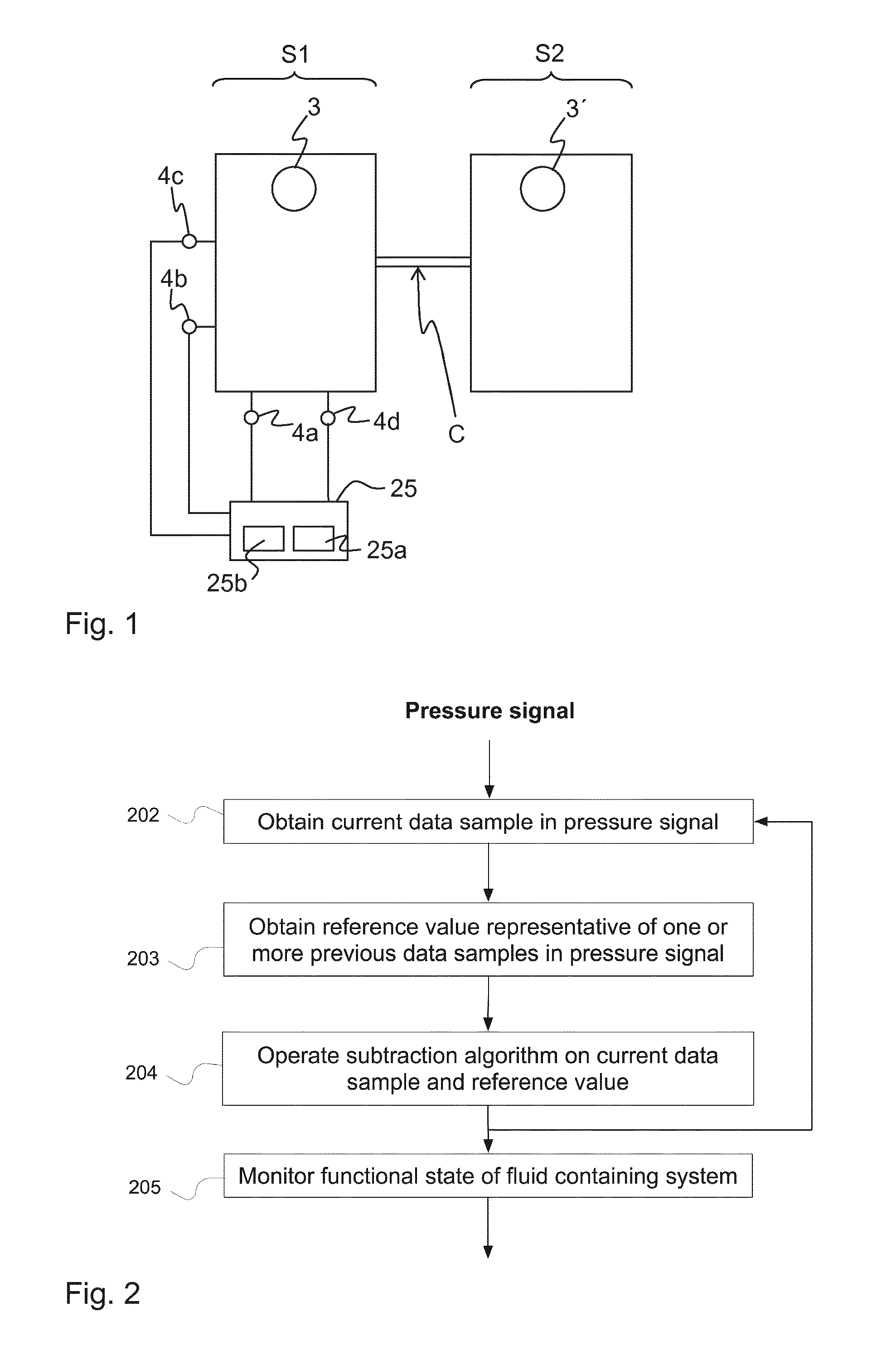
[0073]FIG. 6 is a schematic diagram of a filter structure 31 that implements the process in FIG. 2 to achieve the data processing indicated in FIG. 3B. In FIG. 6, a block Z−Δ is included to implement a step of obtaining, in t...

example ii

Reference Value Based on Corresponding Cycle-Synchronized Samples of Multiple Preceding Pulse Cycles

[0079]FIG. 3D illustrates a second example with corresponding cycle-synchronized samples of multiple preceding pulse cycles used for obtaining the reference value. FIG. 3D shows a first current data sample C1 from a first position in the current pulse cycle and first, second and third preceding cycle-synchronized data samples P11, P21 and P31 from positions in the first, second and third preceding pulse cycles corresponding to the location of the first current data sample in the first current pulse cycle. The reference value is calculated as an aggregation of the first, second and third data samples P11, P21 and P31. A subtraction algorithm is operated on the current data sample, using the reference value, to generate an output sample which is essentially free of a signal component attributable to the first pulse.

[0080]The procedure is repeated for current sample C2 and its cycle-sync...

example iii

Reference Value Based on Prediction of Samples Adjacent to the Current Sample

[0088]FIG. 3H illustrates a third example where the reference value is obtained based on the two preceding data samples P1N and P1N−1 that are adjacent to the current data sample C1 in the pressure signal. The reference value is calculated by extrapolating the two preceding data samples P1N and P1N−1. The filter structure 31 in FIG. 9 may be implemented by setting M=2 and Δ=1 (i.e. a delay of one time step) to achieve the data processing in FIG. 3H. Each preceding data sample is multiplied in the multiplication blocks X with a respective weight factor (W1 to Wm) and added together in the summation blocks Σ to generate an extrapolated or predicted reference value {circumflex over (d)}(n). A subtraction algorithm is operated on a current data sample C1, using the predicted reference value {circumflex over (d)}(n), to generate an output sample e(n) which is essentially free of a signal component attributable t...


PUM

PropertyMeasurementUnit
frequencyaaaaaaaaaa
frequencyaaaaaaaaaa
pressureaaaaaaaaaa

Abstract

A device removes first pulses in a pressure signal of a pressure sensor which is arranged in a fluid containing system to detect the first pulses, which originate from a first pulse generator, and second pulses, which originate from a second pulse generator. The first pulse generator operates in a sequence of pulse cycles, each pulse cycle resulting in at least one first pulse. The device repetitively obtains a current data sample, calculates a corresponding reference value and subtracts the reference value from the current data sample. The reference value is calculated as a function of other data sample(s) in the same pressure signal. The fluid containing system may include an extracorporeal blood flow circuit, e.g. as part of a dialysis machine, and a cardiovascular system of a human patient.

Description

TECHNICAL FIELD[0001]The present invention generally relates to processing of a time-dependent pressure signal obtained from a fluid containing system, and in particular to filtering of such a pressure signal for removal of a signal component originating from a specific pulse generator. The present invention is e.g. applicable in fluid containing systems for extracorporeal blood treatment.BACKGROUND ART[0002]The above-mentioned pressure signal contains both an information component, e.g. pressure variations representing heart pulses, and a disturbance component, e.g. pressure variation caused by a blood pump. It is a challenging task to extract the information component by removing the disturbance component. For this purpose, existing methods have for instance employed an additional pressure signal which only contains the disturbance component, which may be referred to as a “pump pressure profile”.[0003]One approach has been presented in WO2009 / 156175, in which the pump pressure pro...

Claims


Application Information

Patent Timeline
Patent Type & Authority Applications(United States)
IPC IPC(8): A61M1/36G01L19/00
CPCG01L19/00A61M1/3607A61B5/02108A61B5/6866A61B5/7217A61M1/3653A61M1/3656A61M1/3621A61M1/34A61M2205/3331A61M2205/3368A61M2205/50A61M1/3403A61M1/3659B01D61/30B01D61/32
Inventor OLDE, BOSOLEM, KRISTIANHOLMER, MATTIASSTERNBY, JAN
Owner GAMBRO LUNDIA AB
Why Eureka
Try Eureka