Inductive power transmission system and method for concurrently transmitting digital messages

a technology of digital transmission and inductive power, applied in the direction of exchanging data chargers, inductances, batteries data exchange, etc., can solve the problems of increasing energy costs, and affecting the transmission of digital messages

Active Publication Date: 2014-08-28
POWERMAT TECHNOLOGIES
View PDF0 Cites 72 Cited by
  • Summary
  • Abstract
  • Description
  • Claims
  • Application Information

AI Technical Summary

Benefits of technology

[0051]It is noted that the term ‘resonant frequency’ or ‘effective resonant frequency’ as used herein refers to the frequency of the peak value of a plot of a variable against frequency. It is particularly noted that the resonant frequency effectively increases as a resonant system is damped.

Problems solved by technology

On a global scale, there is increasing concern that the emission of greenhouse gases such as carbon dioxide from the burning of fossil fuels may precipitate global warming.
Moreover, energy resources are limited.
The scarcity of global energy resources alongside geopolitical factors drives the cost of energy upwards.
Energy losses in electrical energy transmission are chiefly due to the incidental heating of current carrying wires.
In many cases this is unavoidable, as current carrying wires are essential for the powering of electrical devices and current carrying wires have resistance.
In other cases the energy losses are unnecessary.
For example, electrical devices are often left running unnecessarily and energy used to power devices which are not being used is truly wasted.
Power losses due to the heating of a cable increase according to the square of the current it carries so energy losses from the cable may increase parabolically.
Furthermore, in the absence of effective energy management, if too many devices draw current from a single cable the current supplied may exceed the permitted level thereby tripping a circuit breaker or blowing a fuse.
Even more seriously, the excessive current may lead to overheating of the cable which is a common cause of fire.
A further unnecessary usage of energy is in powering of devices having onboard power cells.
Furthermore, the energy needlessly consumed charging electrical cells beyond the level necessary for operation of a device increases electricity bills.
This can be difficult to maintain as the resonant frequency of the system may fluctuate during power transmission, for example in response to changing environmental conditions or variations in alignment between primary and secondary coils.
Amongst others, one problem associated with resonant transmission is the high transmission voltages involved.
At high operating voltages, a large amount of heat may be generated by the system resulting in high power losses as well as damage to heat sensitive components.

Method used


Image

  • Inductive power transmission system and method for concurrently transmitting digital messages
  • Inductive power transmission system and method for concurrently transmitting digital messages
  • Inductive power transmission system and method for concurrently transmitting digital messages

Examples


Embodiment Construction

[0102]As required, detailed embodiments of the present invention are disclosed herein; however, it is to be understood that the disclosed embodiments are merely exemplary of the invention that may be embodied in various and alternative forms. The figures are not necessarily to scale; some features may be exaggerated or minimized to show details of particular components. Therefore, specific structural and functional details disclosed herein are not to be interpreted as limiting, but merely as a representative basis for teaching one skilled in the art to variously employ the present invention.

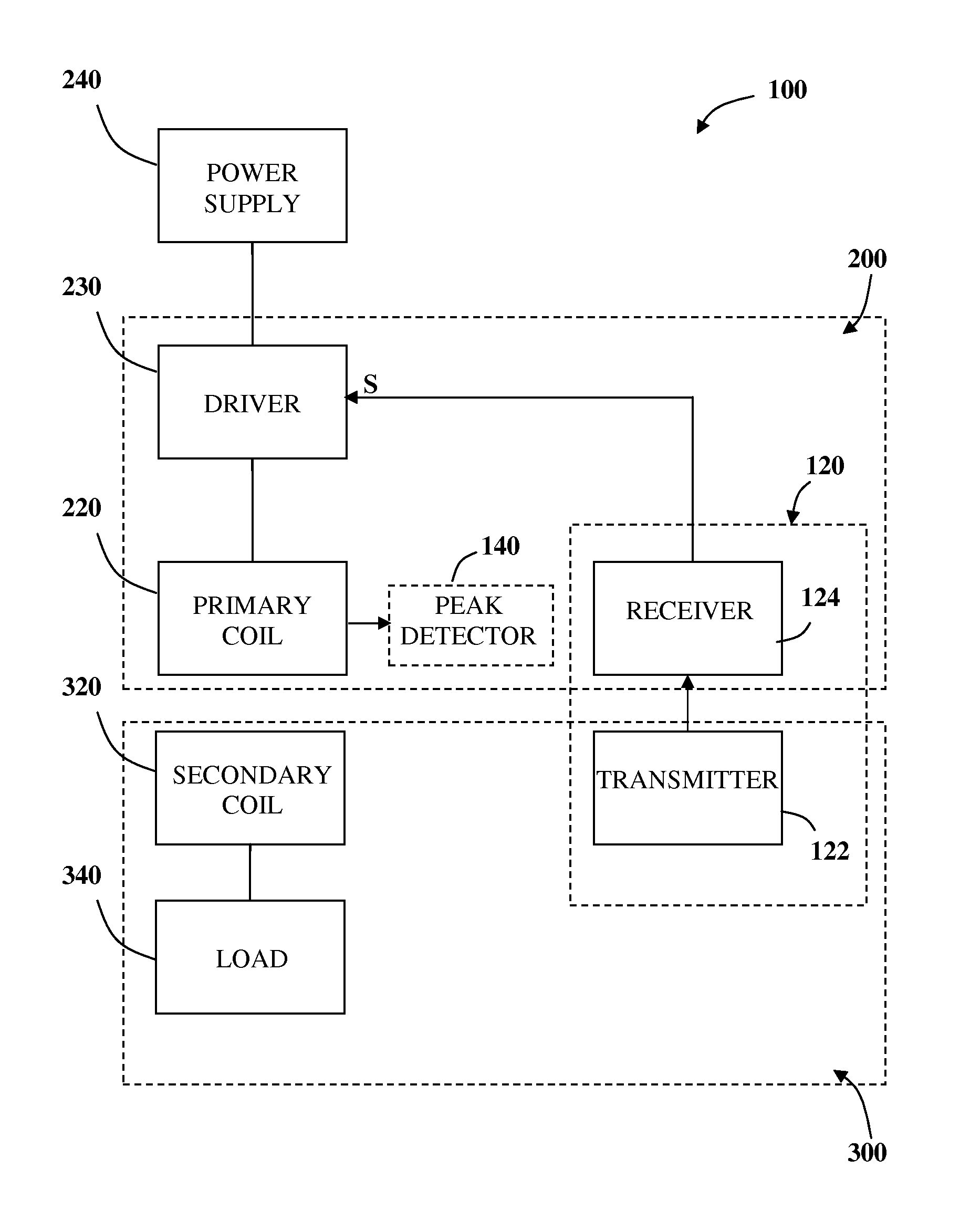
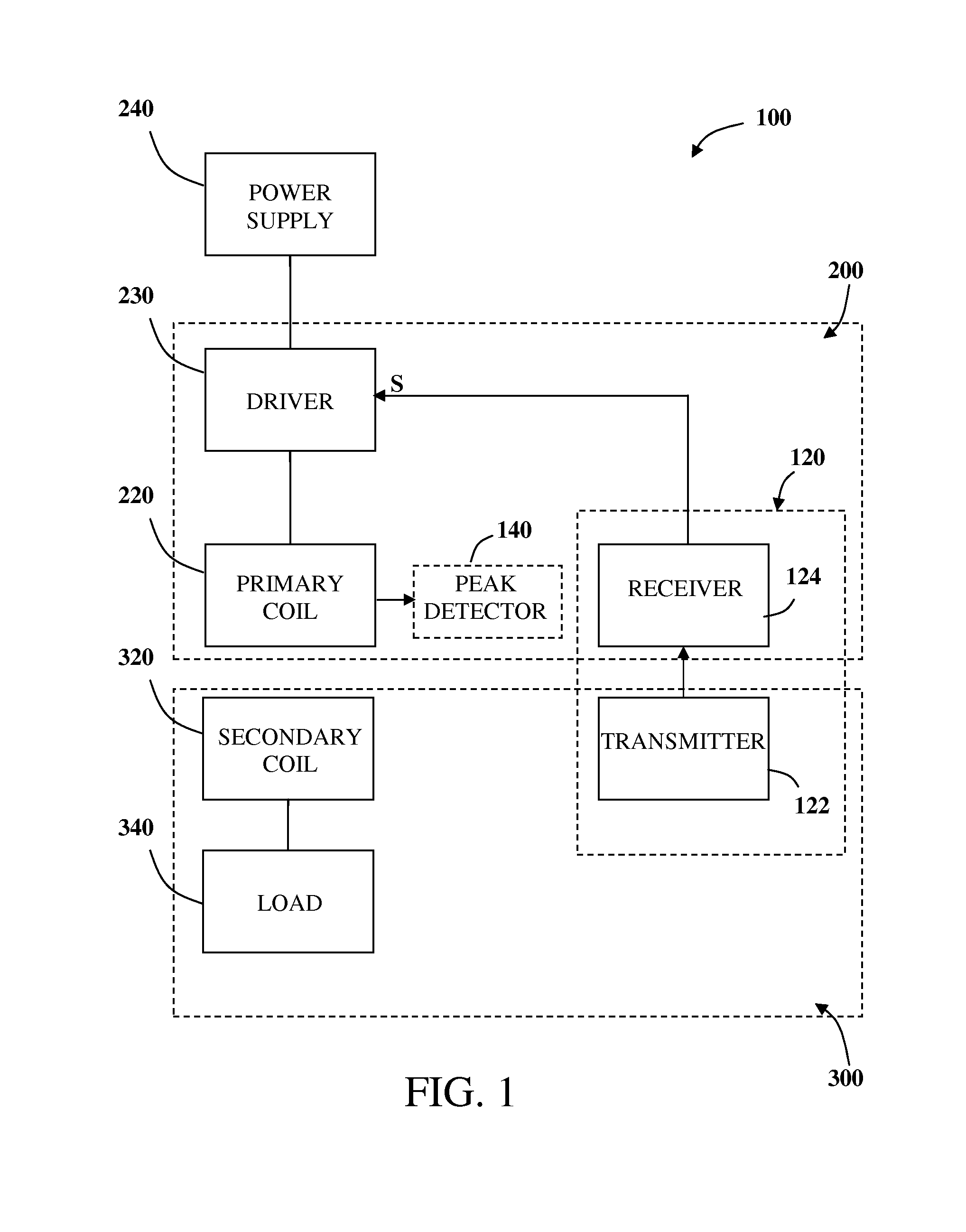
[0103]Reference is now made to FIG. 1 showing a block diagram of the main elements of an inductive power transfer system 100 adapted to transmit power at a non-resonant frequency according to another embodiment of the invention. The inductive power transfer system 100 consists of an inductive power outlet 200 configured to provide power to a remote secondary unit 300. The inductive power outlet 2...


PUM


Abstract

An inductive power receiver including a resonant circuit, a rectifier, a rectified current sense, and a communication and control unit includes a communications modulator and at least one signal generator operable to generate a set of communication signals including a series of pulses generated at characteristic frequencies. Communication signals provide instructions for an inductive power outlet to regulate power transfer to the inductive power receiver.

Description

CROSS-REFERENCE TO RELATED APPLICATIONS[0001]This application is a continuation of PCT / IB2013 / 002288 filed Oct. 11, 2013, which, in turn, claims the benefit of U.S. provisional application Ser. No. 61 / 712,290 filed Oct. 11, 2012, the disclosures of which are hereby incorporated in their entirety by reference herein.FIELD OF THE INVENTION[0002]The present invention is directed to providing energy efficient inductive power transfer. More specifically, the present invention relates to inductive power transfer systems and methods incorporating activation and termination mechanisms.BACKGROUND OF THE INVENTION[0003]The efficient use of available energy is of great importance for a number of reasons. On a global scale, there is increasing concern that the emission of greenhouse gases such as carbon dioxide from the burning of fossil fuels may precipitate global warming. Moreover, energy resources are limited. The scarcity of global energy resources alongside geopolitical factors drives the...

Claims


Application Information

Patent Timeline
Patent Type & Authority Applications(United States)
IPC IPC(8): H04B5/00
CPCH04B5/0037H02J50/10H02J50/80H02J7/00034H02J50/12H02H3/38H02H5/041
Inventor MACH, ELIESERROFE, ARIKGREENWALD, OOLARAVEH, GUYMOSHKOVICH, OZPODKAMIEN, IANKOREN, YUVALBURDO, RINAT
Owner POWERMAT TECHNOLOGIES
Why Eureka
Try Eureka