Inverter Apparatus

a technology of inverter and carrier frequency, which is applied in the direction of motor/generator/converter stopper, starter details, dynamo-electric converter control, etc., can solve the problems of large noise of carrier frequency relative to motor operating noise, and increase the noise of relatively low frequency corresponding to current detection period, so as to improve current detection accuracy and reduce carrier frequency noise

Active Publication Date: 2014-08-28
HITACHI ASTEMO LTD
View PDF7 Cites 35 Cited by
  • Summary
  • Abstract
  • Description
  • Claims
  • Application Information

AI Technical Summary

Benefits of technology

[0011]With a motor apparatus and a motor drive apparatus according to the present invention, ...

Problems solved by technology

However, if the carrier frequency is lowered, the frequency becomes closer to the audible frequency and thus the sound noise of the carrier frequency would raise a problem.
Thus another problem would be raised in which the sound noise of the carrier freq...

Method used


Image

  • Inverter Apparatus
  • Inverter Apparatus
  • Inverter Apparatus

Examples


application example 1

[0059]FIG. 7 is a configuration diagram of an electric power steering system in which the motor apparatus 500 of the embodiment is applied.

[0060]As shown in FIG. 7, the electric power steering system includes an electrical actuator, a handle (steering) 900, a steering detector 901, and an operational amount instructor 903. Operational forces of the handle 900 handled by operators assist the torque using the electrical actuator.

[0061]The electrical actuator includes a torque transmission mechanism 902, the motor 300, and the motor drive apparatus 100. The electrical actuator uses a torque command τ* as the steering assist torque command of the handle 900, and decreases the steering force of the operator using the output from the motor 300.

[0062]In the electrical actuator, the motor drive apparatus 100 receives, as an input command, the assist torque command τ* generated by the operational amount instructor 903. The motor drive apparatus 100 controls the motor current using the torque...

application example 2

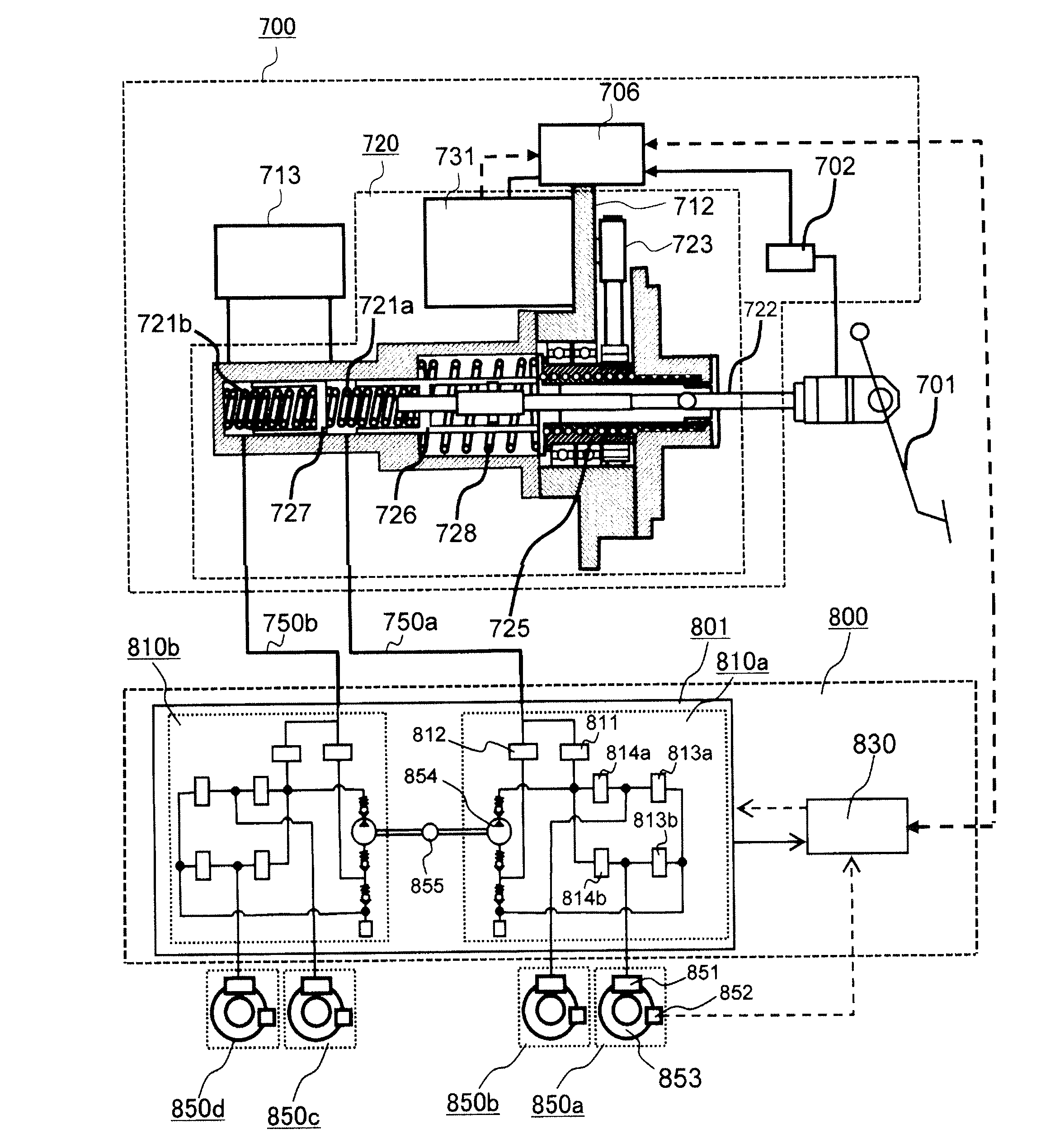
[0069]FIG. 8 is a system block diagram showing a configuration of a car brake system in which the motor apparatus 500 of the embodiment is applied.

[0070]The assist control unit 706 in FIG. 8 is programmed, in the microcomputer, so that the unit has the function same as the motor drive apparatus 100 to perform car brake operations. The motor 731 in the application example 2 is different from the application example 1 in that the motor 731 is integrally mounted to a brake assist apparatus 700. In addition, the application example 2 is different from the application example 1 in that the assist control unit 706 is integrally configured using the casing 712.

[0071]The car brake system includes a brake pedal 701, the brake assist apparatus 700, a brake adjuster 800, and wheel brake mechanisms 850a-850d.

[0072]The brake assist apparatus 700 includes an assist mechanism 720, a master cylinder 721 comprising a primary fluid chamber 721a and a secondary fluid chamber 721b, and a reservoir tan...


PUM


Abstract

An objective of the present invention is to improve current detection accuracy and to reduce noise of carrier frequency. A motor apparatus and a motor drive apparatus calculate motor currents Iu, Iv, and Iw using a DC bus current detected value Idc of an inverter and control a magnitude and a phase of an applied voltage of a motor to drive the motor. A carrier adjuster decreases a carrier frequency Fc of the inverter if a motor output is relatively larger and that increases the carrier frequency Fc of the inverter if the motor output is relatively smaller. A pulse shift adjuster shifts an interphase waveform of a PWM pulse according to the carrier frequency Fc.

Description

TECHNICAL FIELD[0001]The present invention relates to a motor apparatus and a motor drive apparatus that calculate three-phase motor current using DC (direct current) bus current detected value of inverter to control the motor.BACKGROUND ART[0002]In the field of motor apparatus using synchronous motor, a method is known in which a DC bus current of an inverter is detected for reducing the number of electric current sensors detecting three-phase motor current. In this method, in order to appropriately control the motor current, it is desirable to calculate the three-phase motor current from the DC bus current of the inverter, thereby appropriately controlling the magnitude and the phase of the applied voltage to drive the motor.[0003]Patent Literatures 1 and 2 indicated below describe techniques in which a PWM carrier frequency of an inverter is configured to be variable when detecting a DC bus current, thereby improving the detection accuracy of the DC bus current.CITATION LISTPaten...

Claims


Application Information

Patent Timeline
IPC IPC(8): H02P6/10H02P27/06H02P27/08
CPCH02P6/10H02P27/085
Inventor AJIMA, TOSHIYUKIFURUKAWA, KIMIHISAAOYAGI, SHIGEHISAYAMAGUCHI, TOHMAGOTO, DAISUKEKASHIMA, MASAKI
Owner HITACHI ASTEMO LTD
Why Eureka
Try Eureka