Light source device

a light source and light chip technology, applied in the direction of semiconductor devices for light sources, point-like light sources, lighting and heating apparatus, etc., can solve the problems of short service life, poor energy conversion efficiency, and about a half of the light can be emitted out of led chips, so as to improve the light extraction efficiency of the light-emitting chip, and reduce the attenuation of the light inside the light-emi

Inactive Publication Date: 2014-08-28
DONGGUAN MASSTOP LIQUID CRYSTAL DISPLAY +1
View PDF2 Cites 11 Cited by
  • Summary
  • Abstract
  • Description
  • Claims
  • Application Information

AI Technical Summary

Benefits of technology

[0005]An objective of the invention is to provide a light source device, which has a light-emitting assembly emitting light from its two opposite sides toward a reflective cup, so that the attenuation of the light is depressed so as to improve the light extraction efficiency of the light source device.
[0006]The light source device of the invention includes a reflective cup and at least one light-emitting assembly disposed inside the reflective cup. The reflective cup has an opening. The opening has an opening direction. The light-emitting assembly includes a light transmissive substrate, at least one light-emitting chip, and an electrode circuit. The light-emitting chip includes a first light-emitting surface and a second light-emitting surface. Therein, the first light-emitting surface of the light-emitting chip is mounted on the light transmissive substrate in a flip-chip way. The light-emitting chip provides a first light and a second light. The first light is emitted from the first light-emitting surface. The second light is emitted from the second light-emitting surface. The electrode circuit is disposed on the light transmissive substrate and electrically connected to the light-emitting chip. Thereby, after the first light leaves the first light-emitting surface, the first light passes through the light transmissive substrate and out of the light-emitting assembly to be reflected by the reflective cup to be emitted out of the reflective cup through the opening. The second light is emitted out of the light-emitting assembly in a direction away from the light transmissive substrate to be reflected by the reflective cup to be emitted out of the reflective cup through the opening. Therefore, the times of internal reflection in the light-emitting chip of the light generated from two sides of a light-emitting layer of the light-emitting chip can be reduced, so as to improve the light extraction efficiency of the light-emitting chip. Compared with a case in the prior art that the conventional light-emitting chip is provided with a reflection layer on its bottom for reflecting light, the light-emitting chip of the invention is provided without any reflection layer on its surfaces, so the light generated inside the light-emitting chip is not reflected by the reflection layer and the traveling path of the light inside the light-emitting chip is shorter. Therefore, the attenuation of the light inside the light-emitting chip can be reduced as much as possible, so as further to enhance the light extraction efficiency of the light-emitting chip.
[0007]Furthermore, because the two sides of the light-emitting assembly can emit light to the reflective cup, the lighting area of the light-emitting assembly is increased. Moreover, in an embodiment of the present invention, the optical axis of the light-emitting assembly is not parallel to the opening direction of the reflective cup, compared with the light source device in the prior art that the optical axis of the conventional light-emitting assembly emitting light at single side is parallel to the opening direction of its reflective cup, more of the light of the present invention is distributed by the optical structure of the reflective cup, so as to improve the collimation and uniformity of the light provided by the light source device.

Problems solved by technology

Due to tungsten filaments having poor energy conversion efficiency, and shorter service life, some converging lamps which use a light-emitting diode (LED) as a lighting source rather than the tungsten filament are available on the market.
Therefore, only about a half of the light can be emitted out of the LED chip leading to energy waste.

Method used


Image

  • Light source device
  • Light source device
  • Light source device

Examples


first embodiment

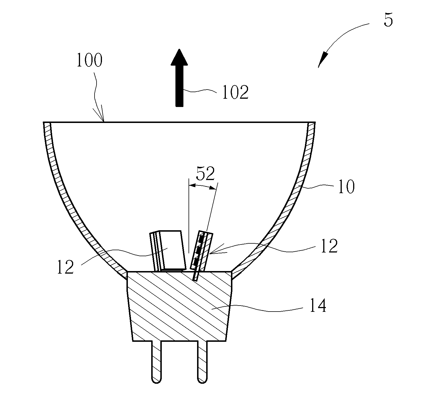
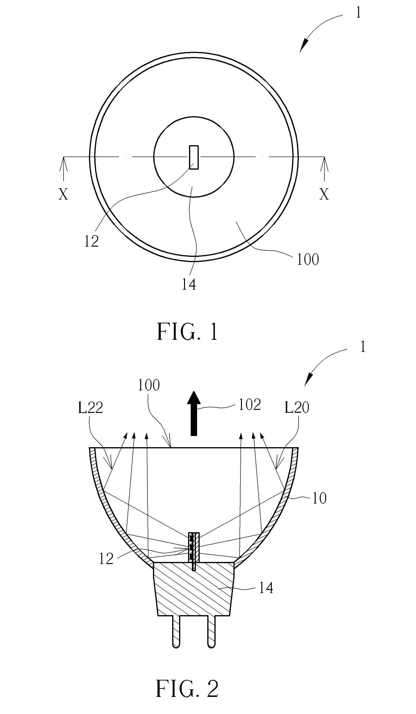
[0020]Please refer to FIG. 1 and FIG. 2. FIG. 1 is a top view of a light source device 1 of a first embodiment according to the invention. FIG. 2 is a sectional view of the light source device 1 along the line X-X in FIG. 1. The light source device 1 includes a reflective cup 10, a light-emitting assembly 12, and a connection socket 14. The reflective cup 10 is a cup shaped structure and has an opening 100. The opening 100 has an opening direction 102 (indicated by an arrow in FIG. 2). The connection socket 14 is connected to the bottom of the reflective cup 10. The light-emitting assembly 12 is disposed inside the reflective cup 10 and electrically connected to the connection socket 14. The light-emitting assembly 12 can emit light L20 and L22 from its two opposite sides. The light L20 and L22 are reflected by the reflective cup 10 to travel toward the opening 100. A portion of the light L20 and L22 is emitted out of the light source device 1 substantially in the opening direction ...

second embodiment

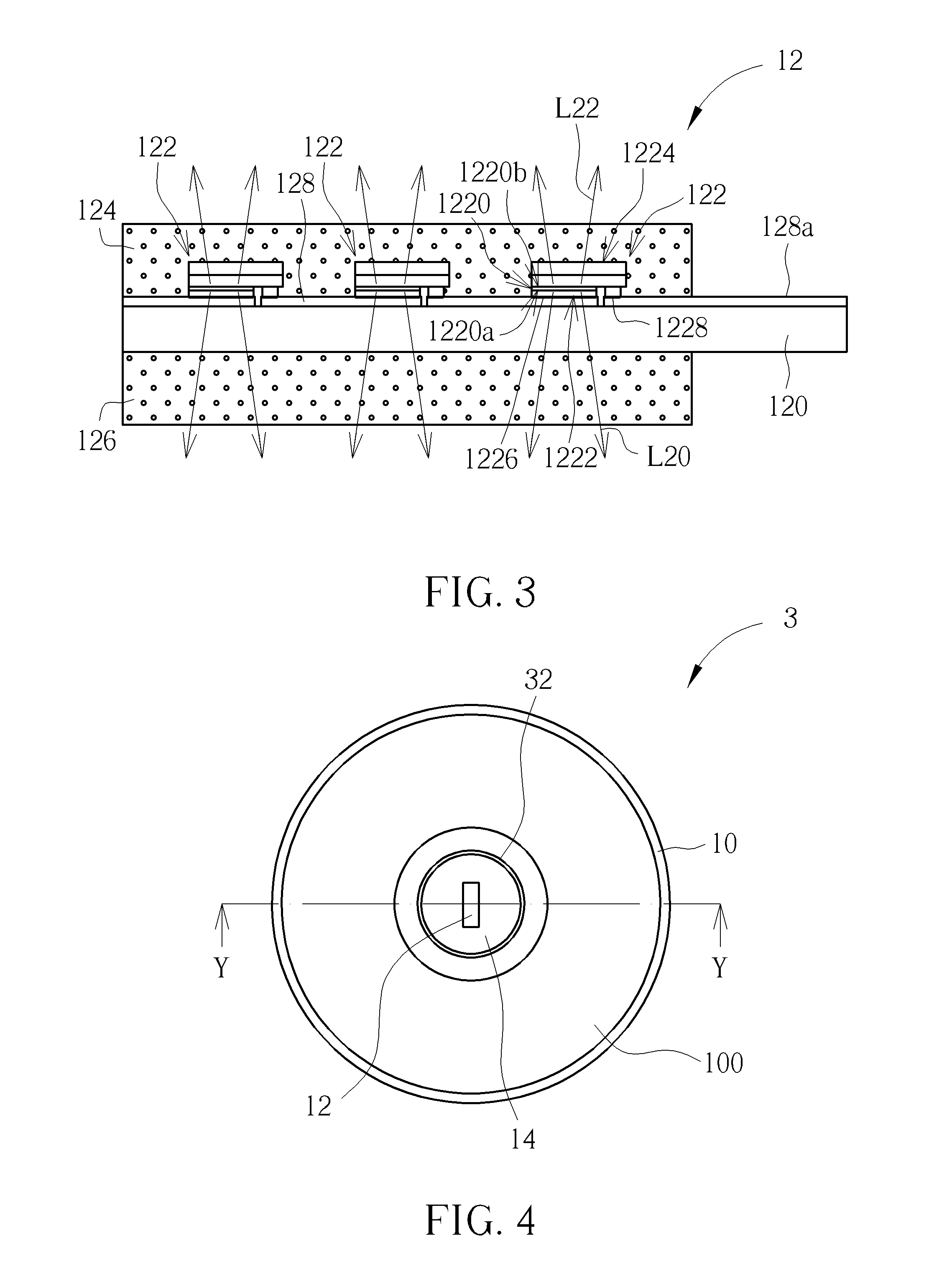
[0024]Please refer to FIG. 4 and FIG. 5. FIG. 4 is a top view of a light source device 3 of a second embodiment according to the invention. FIG. 5 is a sectional view of the light source device 3 along the line Y-Y in FIG. 4. The light source device 3 is substantially similar in structure to the light source device 1; therefore, the light source device 3 still uses the component notations for the light source device 1. The main difference between the light source device 3 and the light source device 1 is that the light source device 3 further includes a diffusion cover 32 disposed inside the reflective cup 10 and surrounding the light-emitting assembly 12 (or the light-emitting chips 122) so that after leaving from the light-emitting assembly 12 (or the light-emitting chips 122), the first light L20 and the second light L22 pass through the diffusion cover 32 and are diffused by the diffusion cover 32 to be reflected by the reflective cup 10 to be emitted out of the reflective cup 1...

third embodiment

[0025]Please refer to FIG. 6, which is a top view of a light source device 4 of a third embodiment according to the invention. The light source device 4 is substantially similar in structure to the light source device 1; therefor, the light source device 4 still uses the component notations for the light source device 1. The main difference between the light source device 4 and the light source device 1 is that the light source device 4 includes three light-emitting assemblies 12. In the light source device 4, the light-emitting assemblies 12 are arranged in a circular configuration inside the reflective cup 10 and electrically connected to the connection socket 14. The first light-emitting surface 1222 and the second light-emitting surface 1224 of each light-emitting chip 122 are parallel to the opening direction 102 of the reflective cup 10. By arranging light-emitting assemblies 12 in a circular configuration, compared with the light source device 1, the light-emitting symmetry o...


PUM


Abstract

A light source device is disclosed and includes a reflective cup, a light-emitting chip, and a light transmissive substrate. The reflective cup has an opening. The light-emitting chip has a light-emitting layer, a first light-emitting surface, and a second light-emitting surface. The first and second light-emitting surfaces are opposite right to a first side and a second side of the light-emitting layer. The light-emitting chip is disposed inside the reflective cup, such that light emitted from the first and second sides emits out of the light-emitting chip through the first and second light-emitting surfaces respectively to be reflected by the reflective cup to be emitted out of the reflective cup through the opening. Therefore, the light extraction efficiency of the light-emitting chip can be improved.

Description

BACKGROUND OF THE INVENTION[0001]1. Field of the Invention[0002]The invention relates to a light source device, and especially relates to a light source device using a reflective cup.[0003]2. Description of the Prior Art[0004]Most conventional converging lamps use tungsten filaments as lighting sources. Due to tungsten filaments having poor energy conversion efficiency, and shorter service life, some converging lamps which use a light-emitting diode (LED) as a lighting source rather than the tungsten filament are available on the market. Light is generated from a quantum well of the LED. Because the refractive index of the LED chip is usually high, the light emitted from the LED chip is substantially distributed in a lambertian manner. Subsequently, the light emitted from the LED chip is converged by a secondary optical lens. Common packages for LED chips use an opaque substrate so that the LED chip emits light at only single side thereof. Therefore, only about a half of the light c...

Claims


Application Information

Patent Timeline
Patent Type & Authority Applications(United States)
IPC IPC(8): F21V7/00
CPCF21V7/00F21V3/049F21V13/08F21K9/23F21Y2107/00F21Y2107/90F21Y2115/10F21V9/30
Inventor CHEN, PING-YENGHUANG, KUO-JUILEE, HSIU-PINGLIN, MING-CHUAN
Owner DONGGUAN MASSTOP LIQUID CRYSTAL DISPLAY
Why Eureka
Try Eureka