Rare-earth magnet and method for producing the same

a technology magnets, applied in the field of rare earth magnets, can solve the problems of insufficient coercivity, inability to suppress the coarsening of crystal grains, and the probability of reducing the coercivity, and achieve excellent coercivity performance and magnetization performance, and suppress the coarsening of nanocrystalline grains

Active Publication Date: 2014-08-28
TOYOTA JIDOSHA KK
View PDF1 Cites 13 Cited by
  • Summary
  • Abstract
  • Description
  • Claims
  • Application Information

AI Technical Summary

Benefits of technology

[0042]As can be understood from the foregoing descriptions, according to the rare-earth magnet and the production method therefor of the present invention, the magnet includes a RE-Fe—B-based main phase with a nanocrystalline structure (where RE is at least one of Nd or Pr) and a grain boundary phase around the main phase, the grain boundary phase containing a RE-X alloy (where X is a metallic element other than heavy rare-earth elements). Crystal grains of the main phase are oriented along the anisotropy axis, and each crystal grain of the main phase, when viewed from a direction perpendicular to the anisotropy axis, has a plane that is quadrilateral in shape or has a close shape thereto. A low-melting-point modifying alloy, such as a Nd—Cu alloy or a Nd—Al alloy, that contains no heavy rare-earth elements such as Dy or Tb is used, and a melt of the modifying alloy is caused to liquid-phase infiltrate into the grain boundary phase in the molten state, whereby it is possible to suppress coarsening of the nanocrystalline grains that form the main phase, and thus provide a rare-earth magnet with excellent coercivity performance and magnetization performance without using expensive heavy rare-earth metals.

Problems solved by technology

However, when heat treatment is performed in the temperature range as high as about 850 to 1050° C., the crystal grains will become coarse, which can result in decreased coercivity with high probability.
That is, even though Dy or Tb is diffused into the grain boundaries, it becomes consequently impossible to sufficiently increase the coercivity.
Consequently, it would be impossible to suppress coarsening of the crystal grains.

Method used


Image

  • Rare-earth magnet and method for producing the same
  • Rare-earth magnet and method for producing the same
  • Rare-earth magnet and method for producing the same

Examples


Embodiment Construction

[0050]Hereinafter, embodiments of a rare-earth magnet of the present invention and a method for producing the same will be described with reference to the drawings.

(Method for Producing Rare-Earth Magnet)

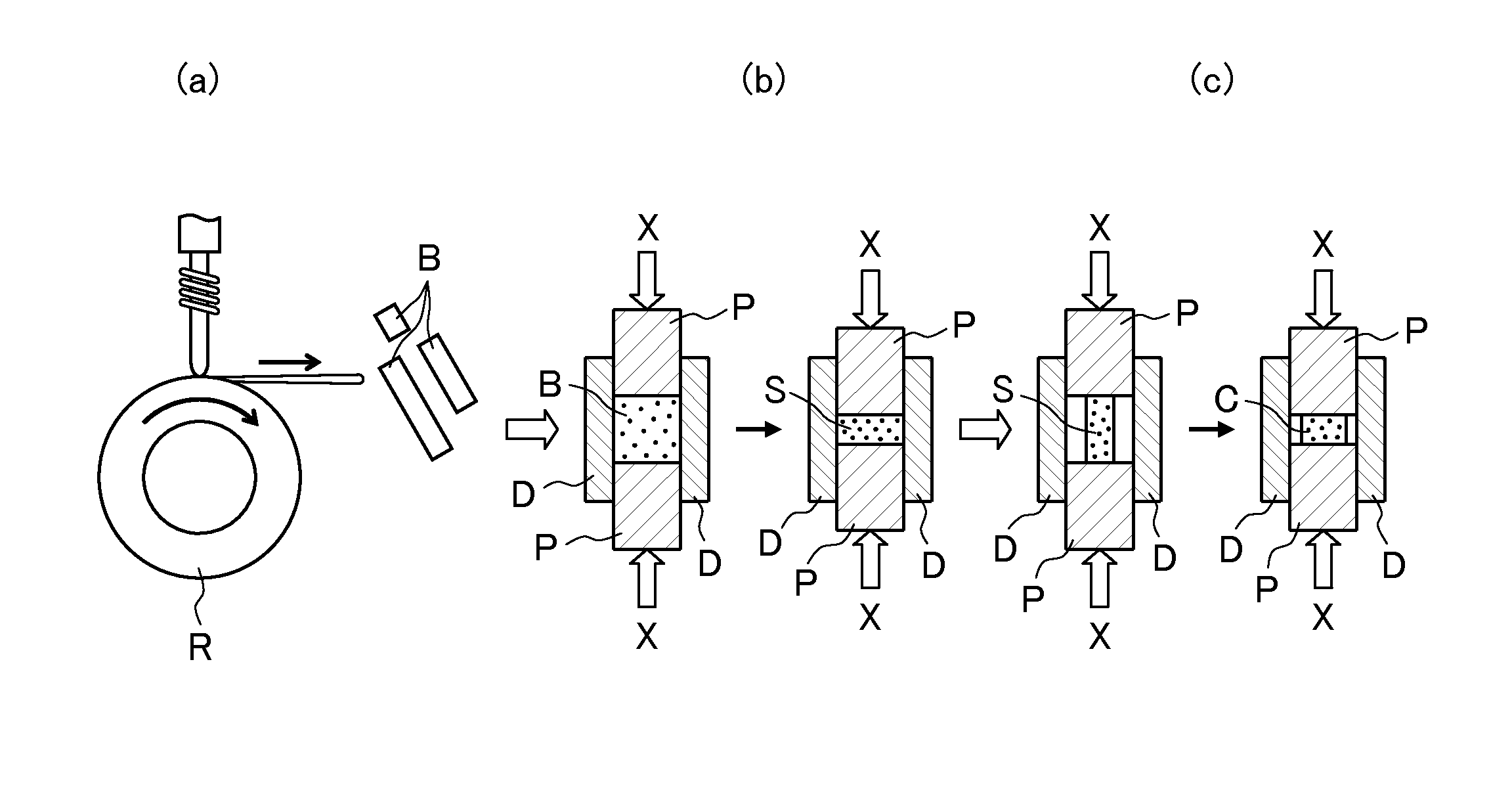
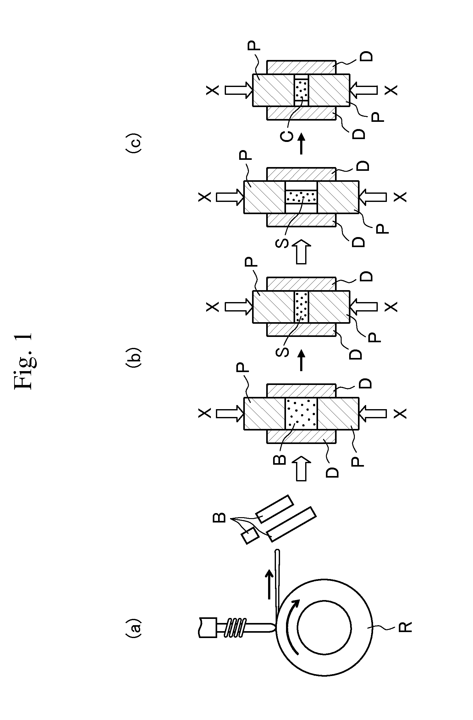
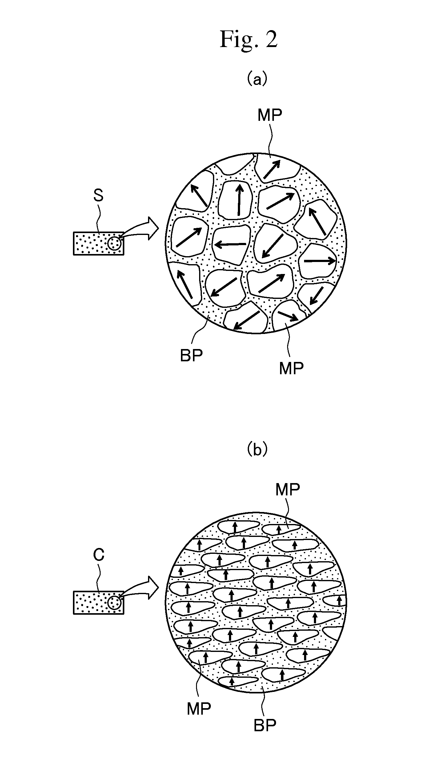
[0051]FIGS. 1(a), (b), and (c) are schematic views sequentially illustrating a first step of a method for producing a rare-earth magnet of the present invention, and FIG. 3(a) is a view illustrating a second step of the production method. In addition, FIG. 2(a) is a view illustrating the micro-structure of a sintered body shown in FIG. 1(b), and FIG. 2(b) is a view illustrating the micro-structure of the molded body in FIG. 1(c). Further, 3(b) is a view illustrating the micro-structure of a rare-earth magnet whose structure is being modified by a modifying alloy, and FIG. 3(c) is a view illustrating the micro-structure of the rare-earth magnet whose structure has been modified by the modifying alloy (i.e., the rare-earth magnet of the present invention).

[0052]As shown in FIG. 1(a), ...


PUM

PropertyMeasurementUnit
crystal grain sizeaaaaaaaaaa
temperatureaaaaaaaaaa

Abstract

Provided is a rare-earth magnet containing no heavy rare-earth metals such as Dy or Tb in a grain boundary phase, has a modifying alloy for increasing coercivity (in particular, coercivity under a high-temperature atmosphere) infiltrated thereinto at lower temperature than in the conventional rare-earth magnets, has high coercivity, and has relatively high magnetizability, and a production method therefor. The rare-earth magnet RM includes a RE-Fe—B-based main phase MP with a nanocrystalline structure (where RE is at least one of Nd or Pr) and a grain boundary phase BP around the main phase, the grain boundary phase containing a RE-X alloy (where X is a metallic element other than heavy rare-earth elements). Crystal grains of the main phase MP are oriented along the anisotropy axis, and each crystal grain of the main phase, when viewed from a direction perpendicular to the anisotropy axis, has a plane that is quadrilateral in shape or has a close shape thereto.

Description

TECHNICAL FIELD[0001]The present invention relates to a rare-earth magnet and a method for producing the same.BACKGROUND ART[0002]Rare-earth magnets that use rare-earth elements, such as lanthanoid, are also called permanent magnets. Such magnets are used not only for hard disks or motors of MRI but also for driving motors of hybrid vehicles, electric vehicles, and the like.[0003]As examples of magnetic performance indices of such rare-earth magnet, residual magnetization (i.e., residual magnetic flux density) and coercivity can be given. However, with a reduction in the motor size and an increase in the amount of heat generation that has been achieved with an increase in the current density, there has been an increasing demand for higher heat resistance of the rare-earth magnet being used. Thus, how to retain the coercivity of a magnet under high-temperature use environments is an important research object to be achieved in the technical field. For example, for a Nd—Fe—B-based magn...

Claims


Application Information

Patent Timeline
Patent Type & Authority Applications(United States)
IPC IPC(8): H01F1/055H01F41/02
CPCB22F3/10C22C28/00H01F41/0253H01F41/0293H01F1/055H01F1/0577B22F3/162B22F3/26B22F2998/10C22F1/16B22F2009/048B22F3/14
Inventor SHOJI, TETSUYAMANABE, AKIRAMIYAMOTO, NORITAKAHIRAOKA, MOTOKIOMURA, SHINYAICHIGOZAKI, DAISUKENAGASHIMA, SHINYA
Owner TOYOTA JIDOSHA KK
Why Eureka
Try Eureka