Supercharge Your Innovation With Domain-Expert AI Agents!

Catalyst-degradation detection device

a detection device and catalyst technology, applied in the direction of electrical control, exhaust treatment electric control, instruments, etc., can solve the problems of reducing the stoichiometry holding time period that is detected in the above described patent literature 1, the possibility of erroneous determination of degradation, and the reduction of the oxygen adsorption/emission amount of the three-way catalyst, etc., to achieve high precision, reduce the amount of catalyst use, and the effect of high precision

Active Publication Date: 2014-09-11
TOYOTA JIDOSHA KK
View PDF7 Cites 9 Cited by
  • Summary
  • Abstract
  • Description
  • Claims
  • Application Information

AI Technical Summary

Benefits of technology

The patent describes a method for accurately detecting the degradation of a three-way catalyst in an exhaust gas purification system. The method uses the oxygen storage amount and change speed in the catalyst to determine the degradation state of the catalyst. By calculating the oxygen storage amount and change speed during the storage and emission time periods, the method can detect degradation with high precision even when the catalyst is exposed to high temperatures and reduced usage. The method can also identify the specific cause of degradation, such as thermal degradation, dissolved loss, or clogging. Overall, the method improves the ability to diagnose and maintain the performance of the three-way catalyst in exhaust gas purification systems.

Problems solved by technology

However, reduction of the use amount of the catalyst leads to decrease in the oxygen adsorption / emission amount of the three-way catalyst, and therefore, there arises the problem that the stoichiometry holding time period that is detected in the above described Patent Literature 1 is reduced.
Therefore, if the air-fuel ratio active control is executed, and the exhaust air-fuel ratio at the upstream side of the three-way catalyst is changed from rich to lean, the problem as follows arises.
Accordingly, when the use amount of the catalyst is reduced in the above described Patent Literature 1, there is the possibility of erroneously determining degradation.

Method used


Image

  • Catalyst-degradation detection device
  • Catalyst-degradation detection device
  • Catalyst-degradation detection device

Examples


embodiment 1

Configuration of Catalyst-Degradation Detection Device

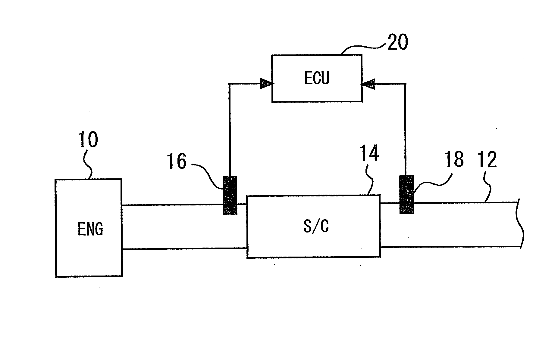
[0055]First, with reference to FIGS. 1 to 7, embodiment 1 of the present invention will be described. FIG. 1 is a view showing a system configuration of a catalyst-degradation detection device of the present embodiment. As shown in FIG. 1, a system of the present embodiment includes an engine 10 as a vehicle power unit. In an exhaust passage 12 of the engine 10, an S / C 14 is disposed. The S / C 14 is a three-way catalyst that efficiently purifies three components of HC, CO and NOx in exhaust emission when an air-fuel ratio of exhaust emission that flows therein is in a narrow range in the vicinity of stoichiometry.

[0056]The three-way catalyst is made by coating a cordierite carrier formed into a honeycomb shape with porous alumina, and causing the alumina to carry precious metal catalysts such as platinum (Pt), palladium (Pd) and rhodium (Rh). Further, by the three-way catalyst, metal cerium (Ce) as an additive is further carried. ...

embodiment 2

[0083]Next, with reference to FIGS. 8 to 12, embodiment 2 of the present invention will be described. In the present embodiment, it is a feature thereof to execute a catalyst degradation detection routine shown in FIG. 11 in the device configuration in FIG. 1. Therefore, description of the device configuration will be omitted.

[Method for Detecting Catalyst Degradation in Embodiment 2]

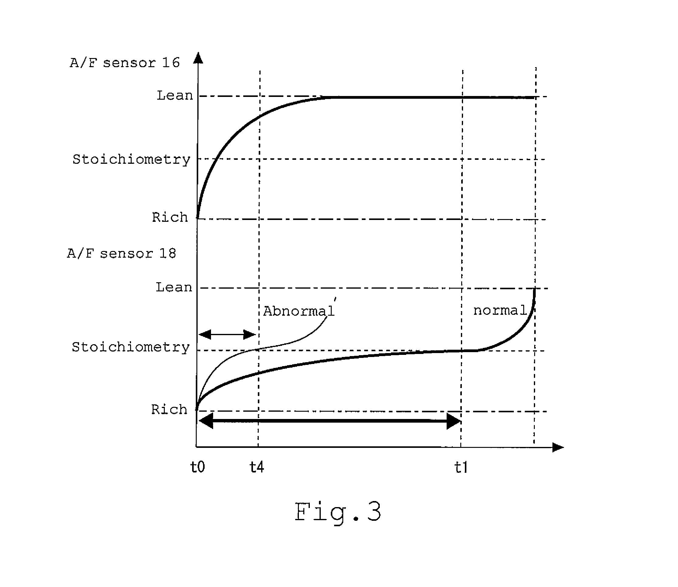
[0084]In the above described embodiment 1, the oxygen storage amount OSA is obtained on the basis of the output value of the A / F sensor 18 until a time just before the downstream side A / F shifts to the lean region in the storage cycle, and until a time just before the downstream side A / F shifts to the rich region in the emission cycle, and degradation relating to the OSC of the three-way catalyst is detected. In the present embodiment, a reaction speed (hereinafter, called “a reaction speed VOSA”) of the exhaust emission purifying reaction is obtained on the basis of the output values of the A / F sensors...

embodiment 3

[0106]Next, with reference to FIGS. 13 to 18, embodiment 3 of the present invention will be described. In the present embodiment, it is a feature thereof to identify a concrete degradation state of the three-way catalyst with use of the oxygen storage amount OSA calculated in the above described embodiment 1, and the reaction speed VOSA calculated in the above described embodiment 2. Therefore, explanation of the device configuration, and the methods for calculating the oxygen storage amount OSA and the reaction speed VOSA will be omitted.

[Method for Detecting Catalyst Degradation in Embodiment 3]

[0107]According to the above described embodiment 1, degradation relating to the OSC of the three-way catalyst can be detected, and according to the above described embodiment 2, degradation relating to the oxidation-reduction capacity of the three-way catalyst can be detected. However, in order to detect degradation of the three-way catalyst with higher precision, they are desirably detect...


PUM


Abstract

An oxygen amount (an oxygen storage amount OSA) stored by metal cerium during a storage cycle is obtained based on an output value of an A / F sensor in a time period immediately before an exhaust air-fuel ratio (a downstream side A / F) detected by the A / F sensor shifts to a lean region, and degradation relating to OSC of the three-way catalyst is detected. In the storage cycle, a target air-fuel ratio is set so that an air-fuel ratio of exhaust emission flowing into an S / C changes from rich to lean. Therefore, the downstream side A / F shifts from stoichiometry to the lean region at a time after reaching stoichiometry. When the three-way catalyst degrades, the downstream side A / F shifts to the lean region from stoichiometry at a time. Therefore, the calculated oxygen storage amount OSA becomes extremely smaller as compared with that at a normal time.

Description

TECHNICAL FIELD[0001]The present invention relates to a catalyst-degradation detection device, and particularly relates to a catalyst-degradation detection device that detects degradation of a three-way catalyst having an exhaust emission purifying function.BACKGROUND ART[0002]There has been conventionally known a device that executes control of forcefully and periodically switching an exhaust air-fuel ratio at an upstream side from a three-way catalyst to a rich side and a lean side from stoichiometry (hereinafter, called “air-fuel ratio active control”), and detects degradation of the three-way catalyst. For example, Patent Literature 1 discloses the catalyst-degradation detection device that detects degradation of a three-way catalyst by using a stoichiometry holding time period of an exhaust air-fuel ratio that is detected by an air-fuel ratio sensor at a downstream side from the three-way catalyst during execution of air-fuel ratio active control.[0003]The three-way catalyst ha...

Claims


Application Information

Patent Timeline
Patent Type & Authority Applications(United States)
IPC IPC(8): F01N11/00
CPCF01N11/007F01N3/101F01N2550/02F01N2560/025F01N2560/14F01N2900/0416F01N2900/1624F02D41/1441F02D41/1456Y02T10/12Y02T10/40
Inventor AOKI, KEIICHIROHAYASHITA, GOSASAKI, TAKANORI
Owner TOYOTA JIDOSHA KK
Features
  • R&D
  • Intellectual Property
  • Life Sciences
  • Materials
  • Tech Scout
  • Unparalleled Data Quality
  • Higher Quality Content
  • 60% Fewer Hallucinations
Learn More