Fixed voltage generating circuit

Inactive Publication Date: 2014-09-11
RICHWAVE TECH CORP
View PDF5 Cites 4 Cited by
  • Summary
  • Abstract
  • Description
  • Claims
  • Application Information

AI Technical Summary

Benefits of technology

[0007]An embodiment of the present invention discloses a fixed voltage generating circuit. The fixed voltage generating circuit comprises a first resistor, a first transistor, a second transistor, a third transistor, a fourth transistor, a second resistor, and a third resistor. The first resistor has a first end and a second end, the second end being coupled to a voltage source. The first transistor has a control end coupled to the first end of the first resistor, a first end coupled to a ground node, and a second end coupled to the control end of the first transistor. The second transistor has a control end coupled to the first end of the first resistor and a first end coupled to the ground node. The third transistor has a control end for receiving a first differential voltage and a first end coupled to a second end of the second transistor. The fourth transistor has a control end for receiving a second differential voltage and a first end coupled to the second end of the second transistor. The second resistor has a first end coupled to a second end of the third transistor and a second end coupled to the voltage source. The third resistor has a first end coupled to a second end of the fourth transistor and a second end coupled to the voltage source. Resistance of the second resistor and resistance of the third resistor are substantially equal.
[0008]Another embodiment of the present invention discloses a fixed voltage generating circuit. The A fixed voltage generating circuit comprises a first resistor, a first transistor, a second transistor, a third transistor, a fourth transistor, a second resistor, and a third resistor. The first transistor has a control end coupled to a first end of the first resistor, a first end coupled to a ground node, and a second end coupled to the control end of the first transistor. The second transistor has a control end coupled to the first end of the first resistor and a first end coupled to the ground node. The third transistor has a control end for receiving a first differential voltage and a first end coupled to a second end of the second transistor. The fourth trans

Problems solved by technology

However the fixed voltage generating circuit is usually fabricated using a CMOS (complementary metal-oxide-semiconductor) process, which includes PMOS (P-type metal-oxide-semiconductor) that is not suitable in a GaAs process.
Thus the fixed voltage generating circuit cannot be integrated and fabri

Method used


Image

  • Fixed voltage generating circuit
  • Fixed voltage generating circuit
  • Fixed voltage generating circuit

Examples


Example

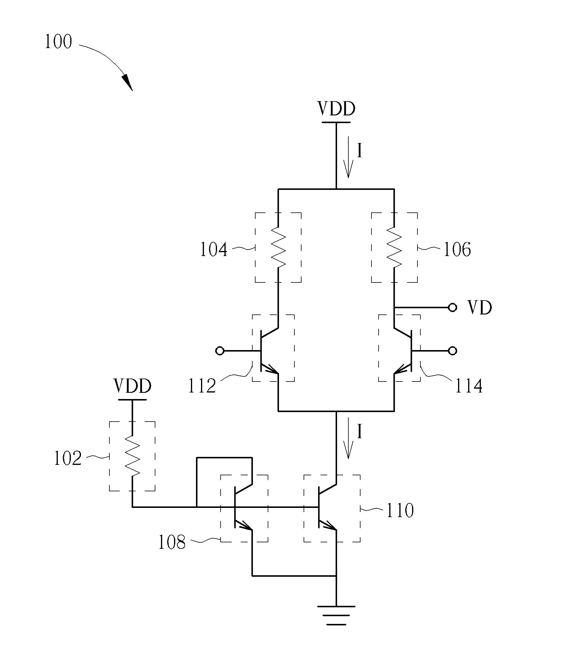
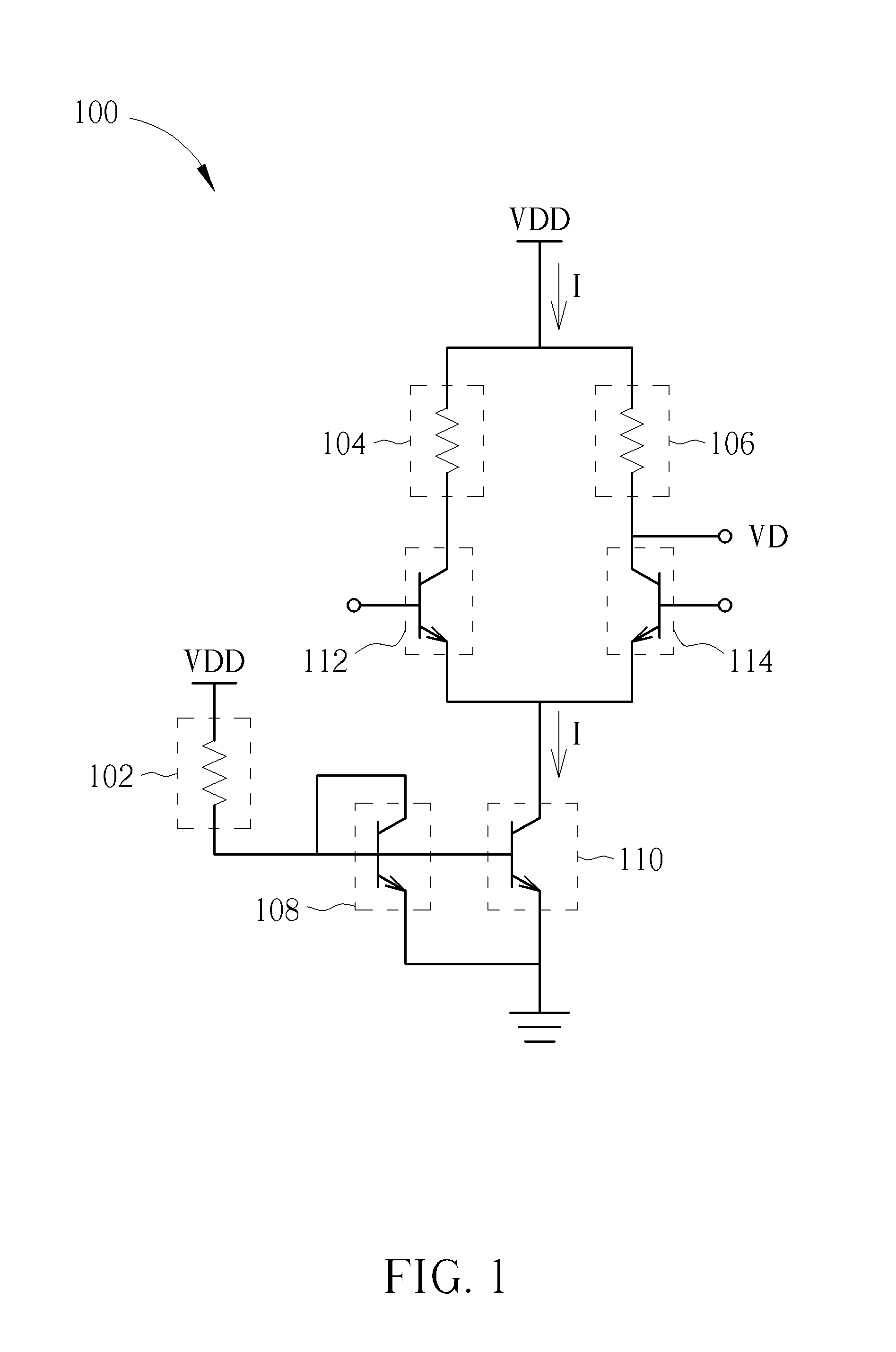
[0015]Please refer to FIG. 1 which is a schematic illustrating a fixed voltage generating circuit 100 according to an embodiment of the present invention. The fixed voltage generating circuit 100 may include a first resistor 102, a second resistor 104, a third resistor 106, a first transistor 108, a second transistor 110, a third transistor 112, and a fourth transistor 114. The first resistor 102 has a first end and a second end, the second end being coupled to a voltage source VDD. The first transistor 108 has a control end coupled to the first end of the first resistor 102, a first end coupled to a ground node, and a second end coupled to the control end of the first transistor 108. The second transistor 110 has a control end coupled to the first end of the first resistor 102 and a first end coupled to the ground node. The third transistor 112 has a control end for receiving a first differential voltage and a first end coupled to a second end of the second transistor 110. The four...


PUM


Abstract

A fixed voltage generating circuit includes a current mirror, a differential pair, and a resistor coupled to the current mirror. A node of the resistor is coupled to a voltage source. The differential pair includes two resistors coupled to the voltage source for enabling the differential pair to output a fixed voltage.

Description

BACKGROUND OF THE INVENTION[0001]1. Field of the Invention[0002]The invention is related to a fixed voltage generating circuit, and more particularly, to a fixed voltage generating circuit fabricated using a GaAs (GALLIUM ARSENIDE) process.[0003]2. Description of the Prior Art[0004]An RF power amplifier fabricated using a GaAs process has good performance and high efficiency, specifically, the RF power amplifier is less prone to signal distortion, has a lower noise to signal ratio, lower power consumption, higher gain, and smaller size. Thus the RF power amplifier gains advantages of shrinking sizes, increasing efficiency, and lowering power consumption of electronic components, and is suitable for use in mobile phones and all ranges of communication devices.[0005]In order that the RF power amplifier fabricated using a GaAs process can function normally under a wide input voltage range, a fixed voltage generated by a fixed voltage generating circuit is provided for operations of the...

Claims


Application Information

Patent Timeline
IPC IPC(8): G05F3/16
CPCG05F3/16H03F3/45085H03F2203/45244H03F2203/45392H03F2203/45508
Inventor CHEN, CHIH-SHENG
Owner RICHWAVE TECH CORP
Why Eureka
Try Eureka