High energy materials for a battery and methods for making and use

a battery and high-energy technology, applied in the field of batteries, can solve the problems of limited widespread use and realization of performance potential poor rate performance, and low efficiency of metal fluoride materials

Inactive Publication Date: 2014-09-18
WILDCAT DISCOVERY TECH
View PDF6 Cites 13 Cited by
  • Summary
  • Abstract
  • Description
  • Claims
  • Application Information

AI Technical Summary

Benefits of technology

[0013]Certain embodiments include the method of making an electrochemical cell containing high-energy cathode materials and methods of use of such electrochemical cells.
[001...

Problems solved by technology

However, a number of technical challenges currently limit their widespread use and realization of their performance potential.
One challenge for certain metal fluoride materials is comparatively poor rate performance.
Unfortunately, one of the drawbacks to wide bandgap materials is the intrinsically low electronic conductivity that results from the wide bandgap.
Such low discharge rates limit the widespread use of metal fluoride active materials.
Another challenge for certain metal fluoride active materials is a significant hysteresis observed between the charge and discharge voltages during cycling.
Since the electrochemical potential for many of the metal fluorides is on the order of 3.0V, this hysteresis of about 1.0V to about 1.5V limits the overall energy efficienc...

Method used


Image

  • High energy materials for a battery and methods for making and use
  • High energy materials for a battery and methods for making and use
  • High energy materials for a battery and methods for making and use

Examples


example 1

Fabrication of Electrodes Using Doped Materials

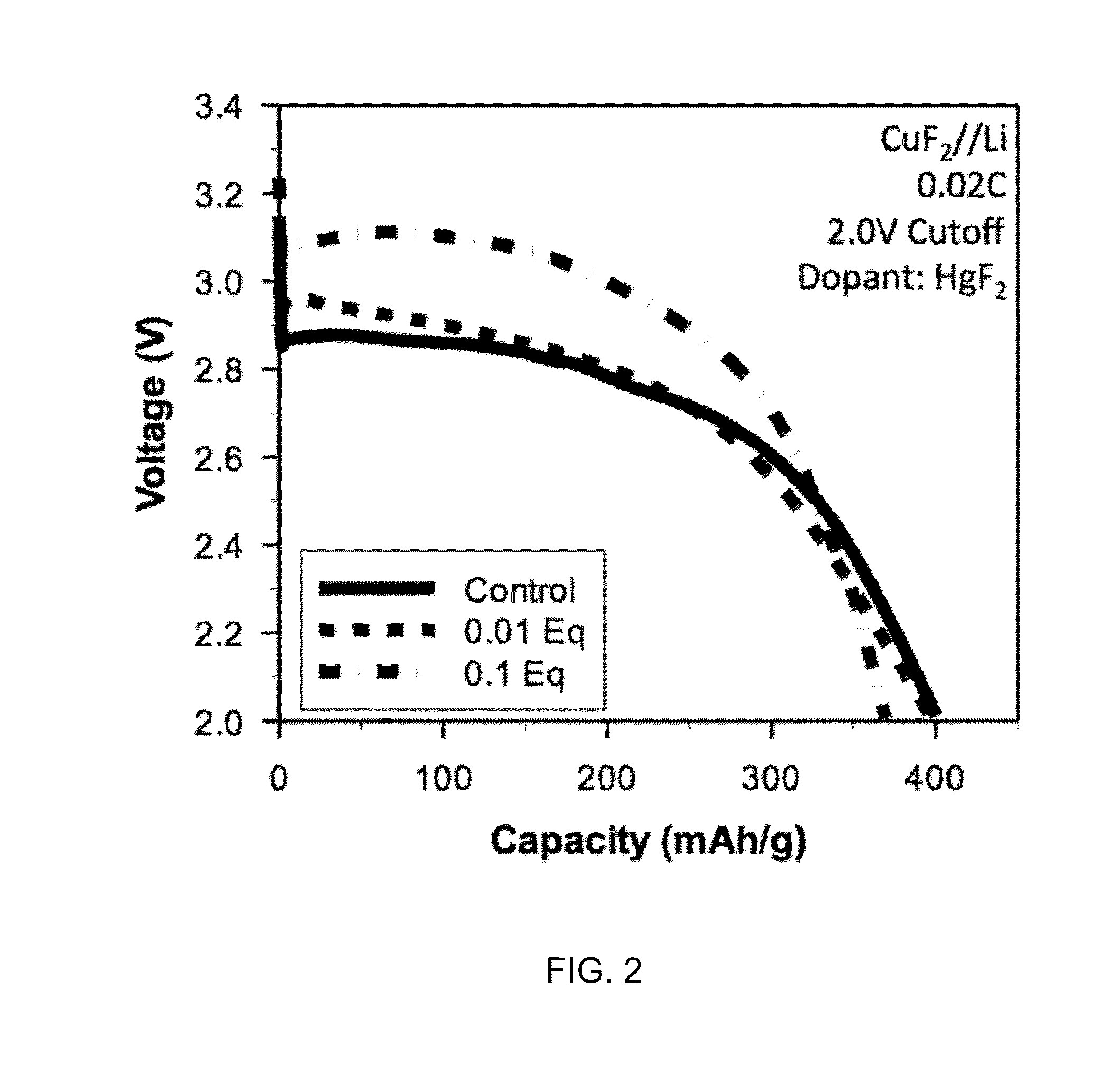
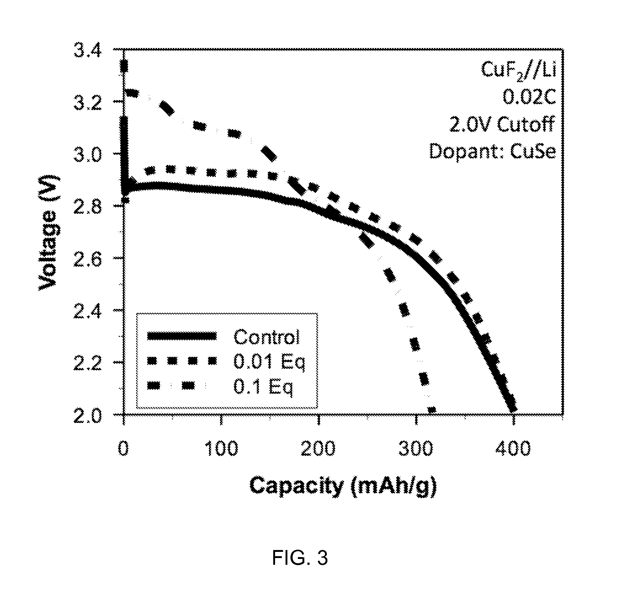
[0041]Synthesis. Doped metal fluoride active materials were synthesized using a process that includes both milling and annealing. Typically, metal fluoride precursors (e.g., CuF2, FeF3) were milled together with the dopant precursor (e.g., HgF2, CuSe), followed by an annealing step. The temperature of the annealing step depends upon the choice of metal fluoride, but is typically performed at 200 degrees C.

[0042]Electrode Formulation. Cathodes were prepared using a formulation composition of 80 wt % active material, 15 wt % binder, and 5 wt % conductive additive according to the following formulation method: about 133 mg PVDF (Sigma Aldrich) and about 44 mg Super P Li (Timcal) was dissolved in 10 mL NMP (Sigma Aldrich) overnight. 70 mg of coated CuF2 powder was added to 1 mL of this solution and stirred overnight. Films were cast by dropping about 70 mL of slurry onto stainless steel current collectors and drying at 150 degrees C. for ab...

example 2

Electrochemical Characterization of Electrochemical Cells Containing Doped Electrodes

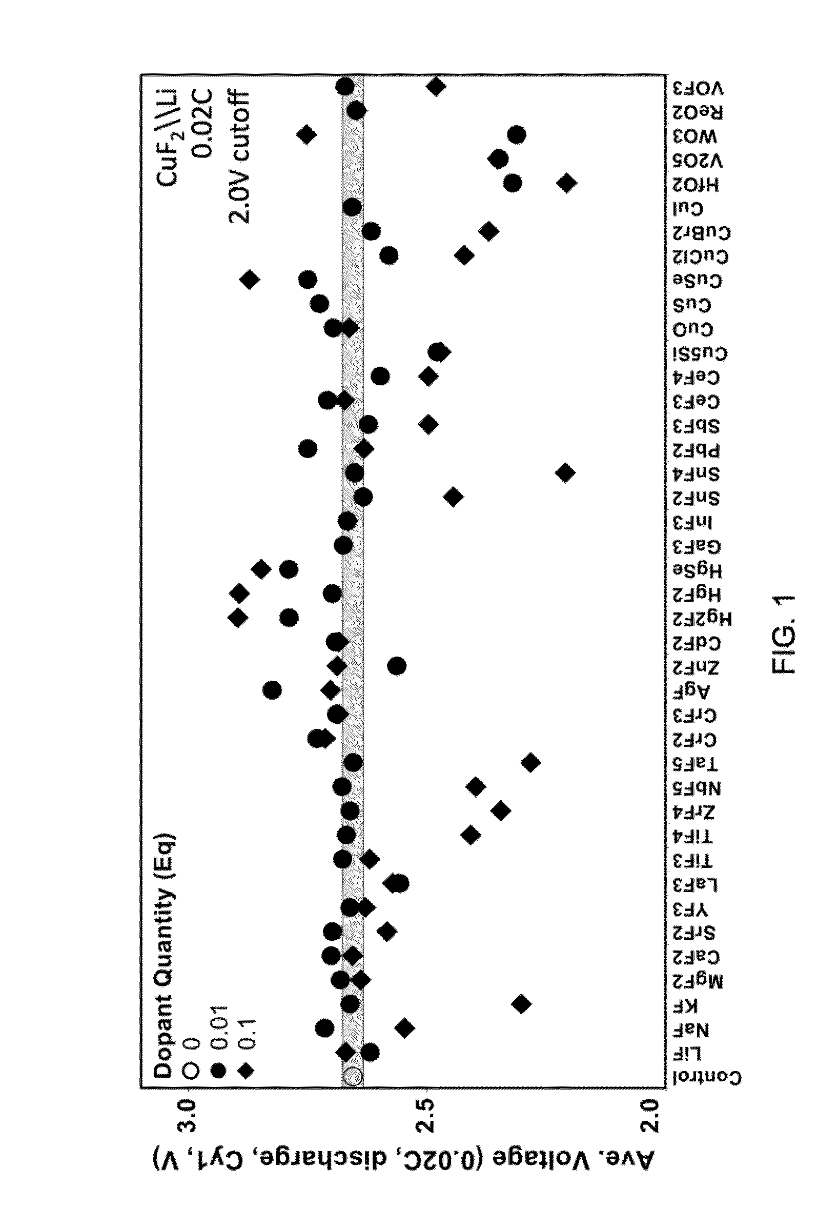
[0043]All batteries were assembled in a high purity argon filled glove box (M-Braun, O2 and humidity contents 6 in 1:2 EC: EMC electrolyte. Electrodes and cells were electrochemically characterized at 30 degrees C. with a constant current C / 50 charge and discharge rate between 4.0 V and 2.0 V. FIGS. 1 through 3 depict certain results of electrochemical characterization.

[0044]Certain embodiments disclosed herein relate to a composition for use in forming a cathode for a battery, and the composition includes a metal fluoride compound doped with a dopant. The addition of the dopant: (i) improves the bulk conductivity of the composition as compared to the undoped metal fluoride compound; (ii) changes the bandgap of the composition as compared to the undoped metal fluoride compound; or (iii) induces the formation of a conductive metallic network. In some embodiments, the metal in the metal fluoride is co...


PUM


Abstract

A composition for forming an electrode. The composition includes a metal fluoride compound doped with a dopant. The addition of the dopant: (i) improves the bulk conductivity of the composition as compared to the undoped metal fluoride compound; (ii) changes the bandgap of the composition as compared to the undoped metal fluoride compound; or (iii) induces the formation of a conductive metallic network. A method of making the composition is included.

Description

CROSS-REFERENCE TO RELATED APPLICATIONS[0001]This application is a continuation of International Application No. PCT / US2014 / 028478, having an international filing date of Mar. 14, 2014 entitled “High Energy Materials For A Battery And Methods For Making And Use,” which claims priority to U.S. Provisional Application No. 61 / 786,598 filed Mar. 15, 2013 entitled “High Energy Materials For A Battery And Methods For Making And Use.” This application claims priority to and the benefit of each of these applications, and each application is incorporated herein by reference in its entirety.BACKGROUND OF THE INVENTION[0002]The present invention is in the field of battery technology, and more particularly in the area of materials for making high-energy electrodes for batteries, including metal-fluoride materials.[0003]One type of battery consists of a negative electrode made primarily from lithium and a positive electrode made primarily from a compound containing a metal and fluorine. During d...

Claims


Application Information

Patent Timeline
IPC IPC(8): H01M4/36C01G3/04C01G49/10
CPCH01M4/364C01G3/04C01G49/10C01P2002/50C01P2006/40H01M4/582H01B1/026H01B1/22G06Q10/0833Y02E60/10H04L67/104
Inventor TONG, WEIKAYE, STEVENKEOGH, DAVIDO'NEILL, CORY
Owner WILDCAT DISCOVERY TECH
Why Eureka
Try Eureka