Force-compensated gradient coil

Active Publication Date: 2014-09-18
SIEMENS HEALTHCARE LTD
View PDF9 Cites 13 Cited by
  • Summary
  • Abstract
  • Description
  • Claims
  • Application Information

AI Technical Summary

Benefits of technology

[0028]An object of the present invention is to reduce the oscillation of bore tubes subjected to oscillating gradient coil magnetic fields, by providing a seconda

Problems solved by technology

However, because of the constant background magnetic field produced by the magnet, those eddy currents produce Lorentz forces, resulting in mechanical vibrations in the bore tube of the OVC.
Mechanical vibration of the gradient coil assembly also causes noise by direct vibration of air within the bore.
These may interfere with imaging, and produce mechanical vibrations and secondary stray fields in that region.
This can result in significant cryogen loss in conventional magnets, and quenching in types of magnets with little or no cryogen inventory, such as the so-called “dry” magnets discussed above.
A particular difficulty arises when, as is typical, the frequency of oscillation of the gradient magnetic fields is close to the resonant frequency of the bore tubes 12b, 14b, 16b.
The oscillations may also interfere with the imaging process, causing detriment to the resulting images.
The resulting oscillations cause acoustic noise which is most unpleasant for a patient in the bore, as well as interfering with imaging and causing heating of cooled components such as the thermal radiation shield and cryogen vessel, if any.
The eddy currents induced in the cryogenically cooled components of the

Method used


Image

  • Force-compensated gradient coil
  • Force-compensated gradient coil
  • Force-compensated gradient coil

Examples


Embodiment Construction

[0034]The present invention provides arrangements in which mechanical vibration of the gradient coil and bore tubes, and gradient coil induced heating (GCIH) resulting from operation of the gradient coil are significantly reduced. Significantly, the present invention allows the reduction in mechanical vibration and GCIH to be achieved without reducing the available radial diameter of the bore of the gradient coil assembly, without increasing the diameter of superconducting coils and without increasing the length of the magnet system.

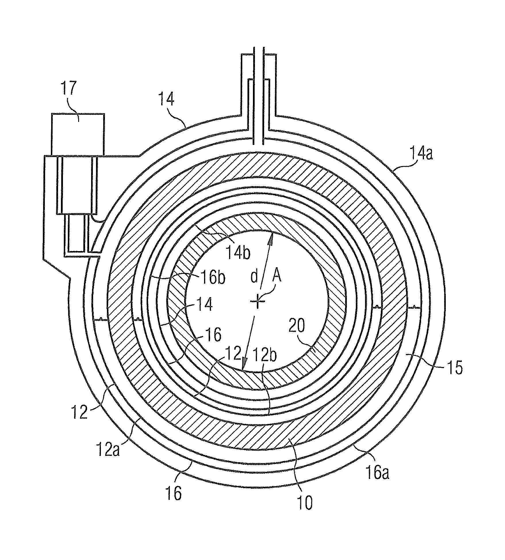
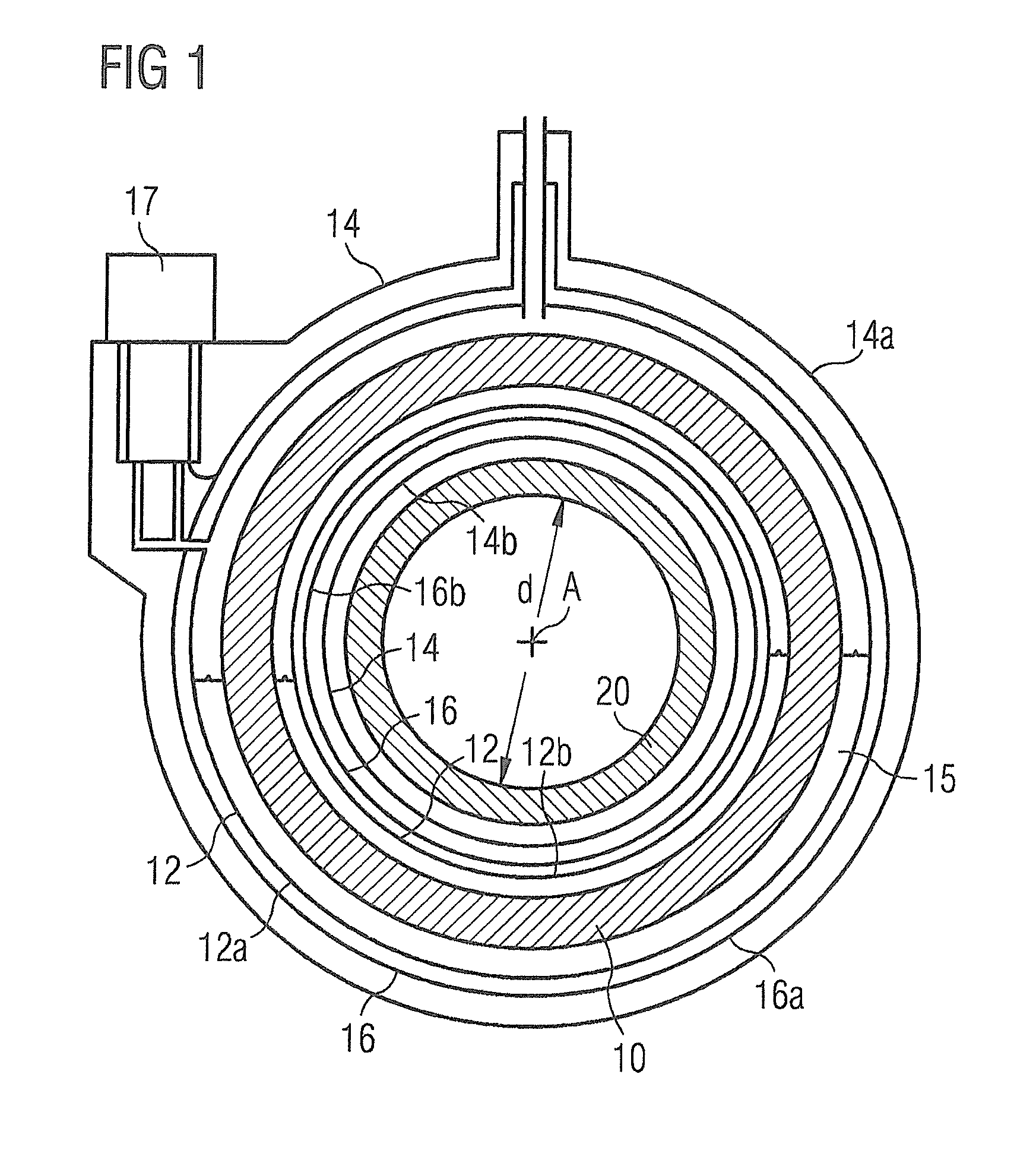
[0035]The present invention provides a method for mechanically compensating for, or balancing, forces generated due to gradient coil-induced eddy currents in conductive structures such as the OVC and thermal radiation shield bore tubes. According to the present invention, this may be achieved by providing a secondary gradient coil radially outside the primary gradient coil, the thermal radiation shield bore tube and the OVC bore tube, which generates mag...


PUM


Abstract

A cylindrical superconducting magnet system for use in magnetic resonance imaging has axially aligned primary superconducting coils that are situated within an outer vacuum chamber (OVC). A thermal radiation shield surrounds the primary superconducting coils within the OVC. A primary gradient coil assembly is axially aligned with the primary superconducting coils and is situated radially within the primary superconducting coils. The cylindrical superconducting magnetic system also includes a secondary gradient coil assembly, that is radially situated outside of the primary superconducting coils and that is mechanically attached to the primary gradient coil assembly.

Description

BACKGROUND OF THE INVENTION[0001]1. Field of the Invention[0002]The present invention relates to cylindrical magnet systems as used in imaging systems such as MRI (Magnetic Resonance Imaging) systems.[0003]2. Description of the Prior Art[0004]FIG. 1 shows a radial cross-section through a typical magnet system for use in an imaging system. A cylindrical magnet 10, typically comprising superconducting coils mounted on a former or other mechanical support structure, is positioned within a cryostat, having a cryogen vessel 12, thermal radiation shield 16 and outer vacuum container (OVC) 14. The cryogen vessel 12 contains a quantity of liquid cryogen 15, for example helium, which holds the superconducting magnet at a temperature below its transition temperature.[0005]The magnet is essentially rotationally symmetrical about axis A-A. The term “axial” is used in the present document to indicate a direction parallel to axis A-A, while the term “radial” means a direction perpendicular to axi...

Claims


Application Information

Patent Timeline
IPC IPC(8): G01R33/3815
CPCG01R33/3815G01R33/3854
Inventor CALVERT, SIMON JAMES
Owner SIEMENS HEALTHCARE LTD
Why Eureka
Try Eureka