Spinal fusion implants and devices and methods for deploying such implants

a technology of spinal fusion and implants, applied in the field of minimally invasive surgical procedures, can solve the problems of affecting the dimensional aspect of at least a portion of the disc, disrupting and disturbing the tissue surrounding the surgical site, and affecting the patient's recovery, so as to achieve the effect of increasing the dimensional aspect of at least a portion

Active Publication Date: 2014-09-18
SPINAL ELEMENTS INC
View PDF12 Cites 76 Cited by
  • Summary
  • Abstract
  • Description
  • Claims
  • Application Information

AI Technical Summary

Benefits of technology

[0024]In one aspect, a tissue distraction device includes first and second elongated members. The first and second elongated members are insertable between tissue layers and adapted to define a structure in situ having a dimensional aspect in a direction extending between the tissue layers. The tissue distraction device also includes an augmenting elongated member insertable between and in contact with the first and second elongated members to spread the first and second elongated members apart to increase the dimensional aspect of at least a portion of the structure in situ. The augmenting, first, and second elongated members are sufficiently flexible to change between a generally linear configuration and a generally less linear configuration. A locking member is configured to be secured to one of the elongated members at a plurality of locations to lock the augmenting, first, and second elongated members in the generally less linear configuration.

Problems solved by technology

Developmental irregularities, trauma, tumors, stress and degenerative wear can cause defects in the spinal column for which surgical intervention is necessary.
Such invasive surgical techniques often disrupt and disturb tissue surrounding the surgical site to the detriment of the patient.
Genetic and biochemical causes can result in changes in the extracellular matrix pattern of the disc and a decrease in biosynthesis of extracellular matrix components by the cells of the disc.
With a loss of water content, the nucleus becomes desiccated resulting in a decrease in internal disc hydraulic pressure, and ultimately to a loss of disc height.
This loss of disc height can cause the annulus to buckle with non-tensile loading and the annular lamellae to delaminate, resulting in annular fissures.
The weight of the person generates a compressive load on the discs, but this load is not uniform during typical bending movements.
Decreased disc height results in increased pressure in the nucleus, which can lead to a decrease in cell matrix synthesis and an increase in cell necrosis and apoptosis.
In addition, increases in intra-discal pressure create an unfavorable environment for fluid transfer into the disc, which can cause a further decrease in disc height.
With decreasing height of the disc, the facet joints bear increasing loads and may undergo hypertrophy and degeneration, and may even act as a source of pain over time.
Decreased stiffness of the spinal column and increased range of motion resulting from loss of disc height can lead to further instability of the spine, as well as back pain.
This decrease may lead to spinal nerve impingement, with associated radiating pain and dysfunction.
The discs that must bear additional loading are now susceptible to accelerated degeneration and compromise, which may eventually propagate along the destabilized spinal column.
However, the sudden decrease in disc volume caused by the surgical removal of the disc or disc nucleus may increase the local and global problems noted above.
During a total discectomy, a substantial amount (and usually all) of the volume of the nucleus pulposus is removed and immediate loss of disc height and volume can result.
Even with a partial discectomy, loss of disc height can ensue.
A challenge in the use of a posterior procedure to install spinal prosthesis devices is that a device large enough to contact the end plates and expand the space between the end plates of the same or adjacent vertebra must be inserted through a limited space.
In the case of procedures to increasing intervertebral spacing, the difficulties are further increased by the presence of posterior osteophytes, which may cause “fish mouthing” or concavity of the posterior end plates and result in very limited access to the disc.
A further challenge in degenerative disc spaces is the tendency of the disc space to assume a lenticular shape, which requires a relatively larger implant than often is easily introduced without causing trauma to the nerve roots.
The size of rigid devices that may safely be introduced into the disc space is thereby limited.
While cages of the prior art have been generally successful in promoting fusion and approximating proper disc height, typically these cages have been inserted from the posterior approach, and are therefore limited in size by the interval between the nerve roots.
Further, it is generally difficult to implant from the posterior approach a cage that accounts for the natural lordotic curve of the lumber spine.
However, despite the use of minimally invasive techniques, the implantation of cage devices for treating the spine typically involves nerve root retraction, an inherently high risk procedure.
However if a device is visible using X-ray technology, then the device can interfere with the detection and monitoring of spinal tissues, such as bone growing into the disc space after a vertebral fusion procedure.

Method used


Image

  • Spinal fusion implants and devices and methods for deploying such implants
  • Spinal fusion implants and devices and methods for deploying such implants
  • Spinal fusion implants and devices and methods for deploying such implants

Examples


Embodiment Construction

[0057]The embodiments disclosed herein are for the purpose of providing a description of the present subject matter, and it is understood that the subject matter may be embodied in various other forms and combinations not shown in detail. Therefore, specific embodiments and features disclosed herein are not to be interpreted as limiting the subject matter as defined in the accompanying claims.

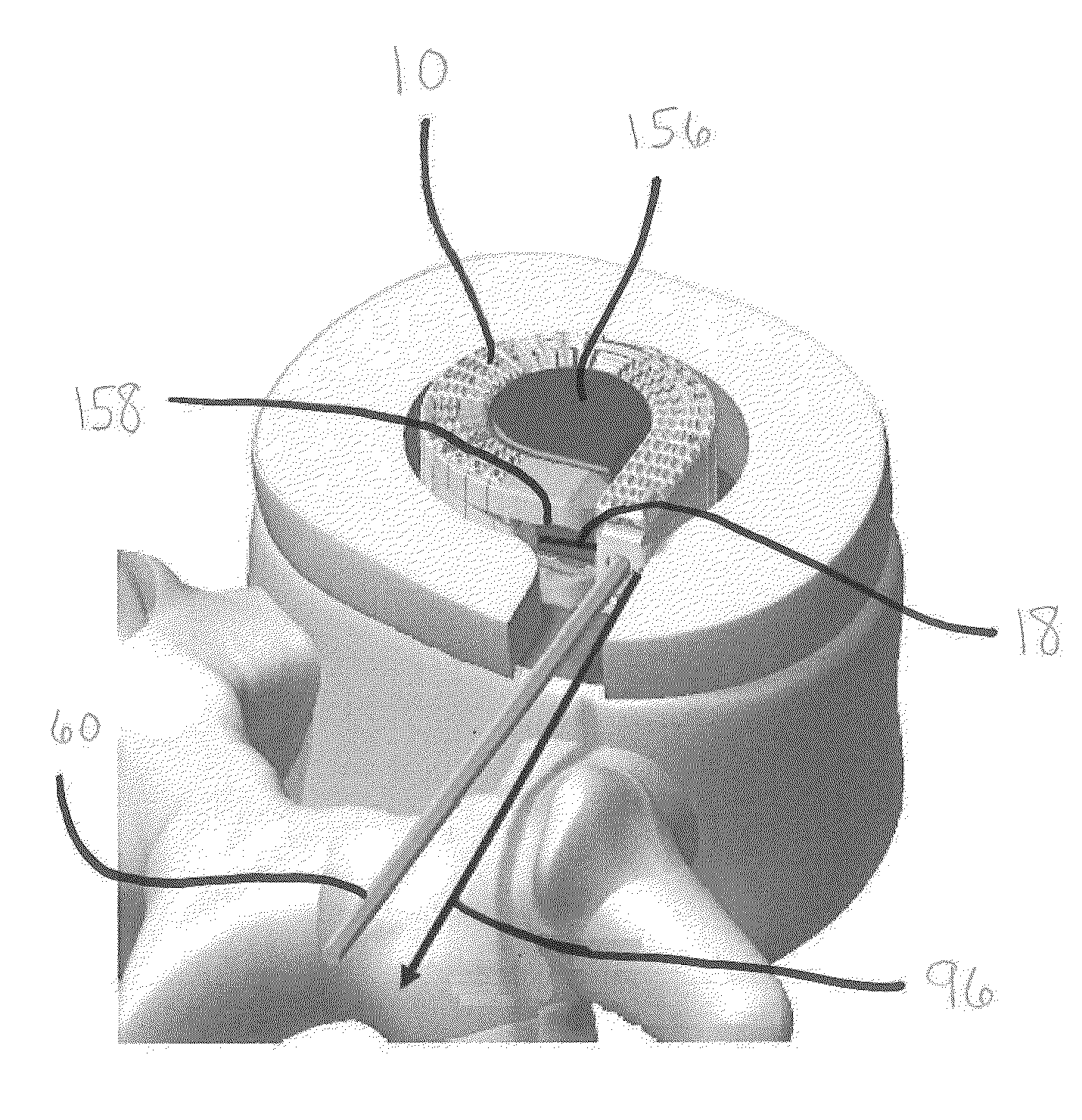
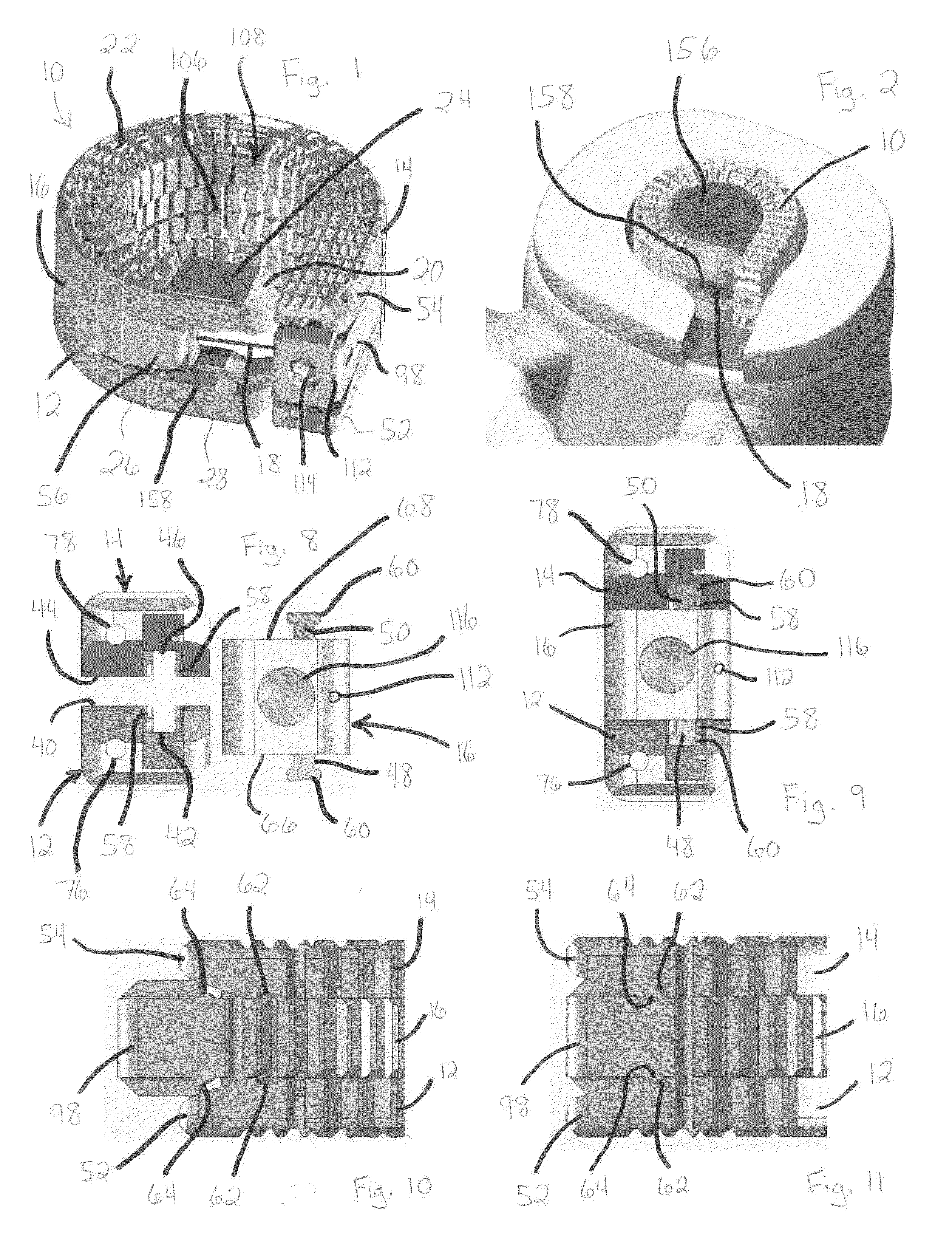
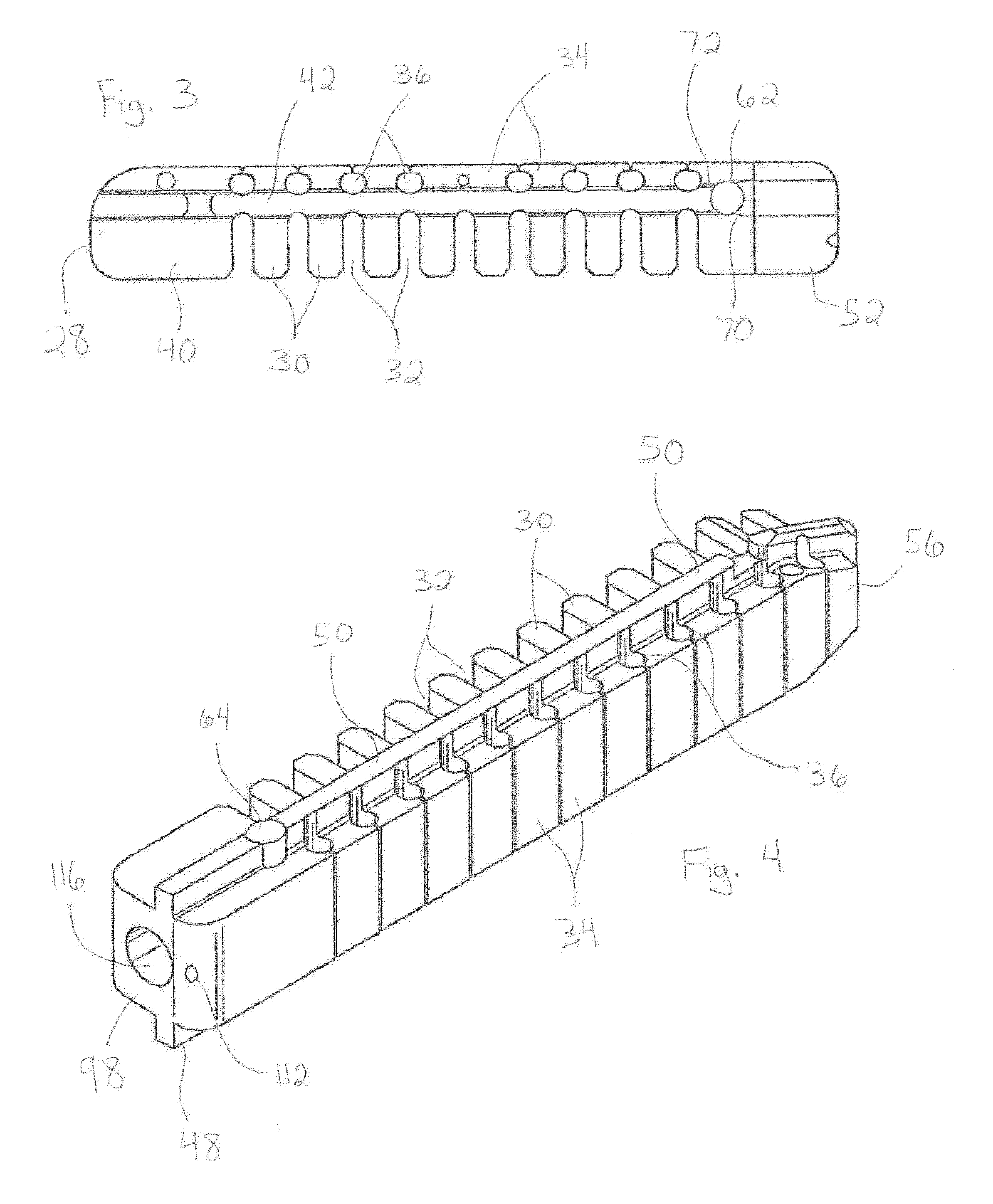
[0058]The devices and methods of the present invention provide multiple features of distraction devices, distraction device support structures and deployment systems that can be used to actively separate tissue layers by engaging them and forcing them apart, or to support the separation of tissue layers separated by the distraction device itself or by other devices or processes or a combination of these.

[0059]As used herein, the terms “distraction device” and “support structure” are intended to have a general meaning and is not limited to devices that only actively separate tissue layers, only ...


PUM


Abstract

Methods and apparatus are disclosed for distracting tissue. The devices and methods may include insertion of first and second elongated members into the space between two tissue layers, with an augmenting elongated member inserted therebetween to form a distraction device between the tissues to be distracted. The distraction device defines a generally annular configuration, with a locking member secured to one of the elongated members at a plurality of locations to maintain the distraction device in the generally annular configuration. The augmenting elongated member may be shorter than the first and second elongated members such that a window is defined between the proximal and distal ends of the augmenting elongated member when the distraction device and the first and second elongated members are in the generally annular configuration. Bone graft material or bone filler may be introduced into the interior of the distraction device through the window.

Description

BACKGROUND[0001]1. Field of the Disclosure[0002]The present invention generally relates to apparatus and methods employed in minimally invasive surgical procedures and more particularly to various aspects of apparatus and methods for separating and / or supporting tissue layers, especially in the disc space of the spine.[0003]2. Description of Related Art[0004]A variety of physical conditions involve two tissue surfaces that, for diagnosis or treatment of the condition, need to be separated or distracted or maintained in a separated condition from one another and then supported in a spaced-apart relationship. Such separation or distraction may be to gain exposure to selected tissue structures, to apply a therapeutic pressure to selected tissues, to return or reposition tissue structures to a more normal or original anatomic position and form, to deliver a drug or growth factor, to alter, influence or deter further growth of select tissues or to carry out other diagnostic or therapeuti...

Claims


Application Information

Patent Timeline
Patent Type & Authority Applications(United States)
IPC IPC(8): A61F2/44
CPCA61F2/442A61F2/4455A61F2/4601A61F2/4611A61B17/8852A61F2002/3008A61F2002/30092A61F2002/30242A61F2002/30383A61F2002/30462A61F2002/30507A61F2002/3082A61F2002/30827A61F2002/4415A61F2002/444A61F2220/0016A61B2017/00867A61F2002/30014A61F2/4603A61F2002/30593A61F2/446
Inventor LEE, JAMESEMERY, JEFFREY L.MCGRATH, TIMOTHYSCHALLER, LAURENTHUFFMASTER, ANDREWQUDDUS, EBRAHIM MOHAMMAD
Owner SPINAL ELEMENTS INC
Why Eureka
Try Eureka