Apparatus and method for liquid sample introduction

Active Publication Date: 2014-09-25
THERMO ELECTRON MFG
View PDF1 Cites 16 Cited by
  • Summary
  • Abstract
  • Description
  • Claims
  • Application Information

AI Technical Summary

Benefits of technology

[0032]The droplet may be of any size suitable for the analysis device. Preferably the droplet size lies in the range 0.1 to 10 μm in diameter. Droplets of this size are suitable for highly efficient direct injection into an inductive

Problems solved by technology

However where the analysis device utilizes a plasma or flame to dissociate and excite or ionize the sample, as both plasmas and flames are inefficient at dissociating large droplets, a spray chamber is usually placed between the nebulizer and the torch so as to exclude large droplets from the sample stream entering the analysis device.
In the cases of ICP-OES and ICP-MS it is well known that only 1-2% of the nebulized sample-containing liquid is in the form of sufficiently small droplets suitable for processing within the torch, and that thi

Method used


Image

  • Apparatus and method for liquid sample introduction
  • Apparatus and method for liquid sample introduction
  • Apparatus and method for liquid sample introduction

Examples


Embodiment Construction

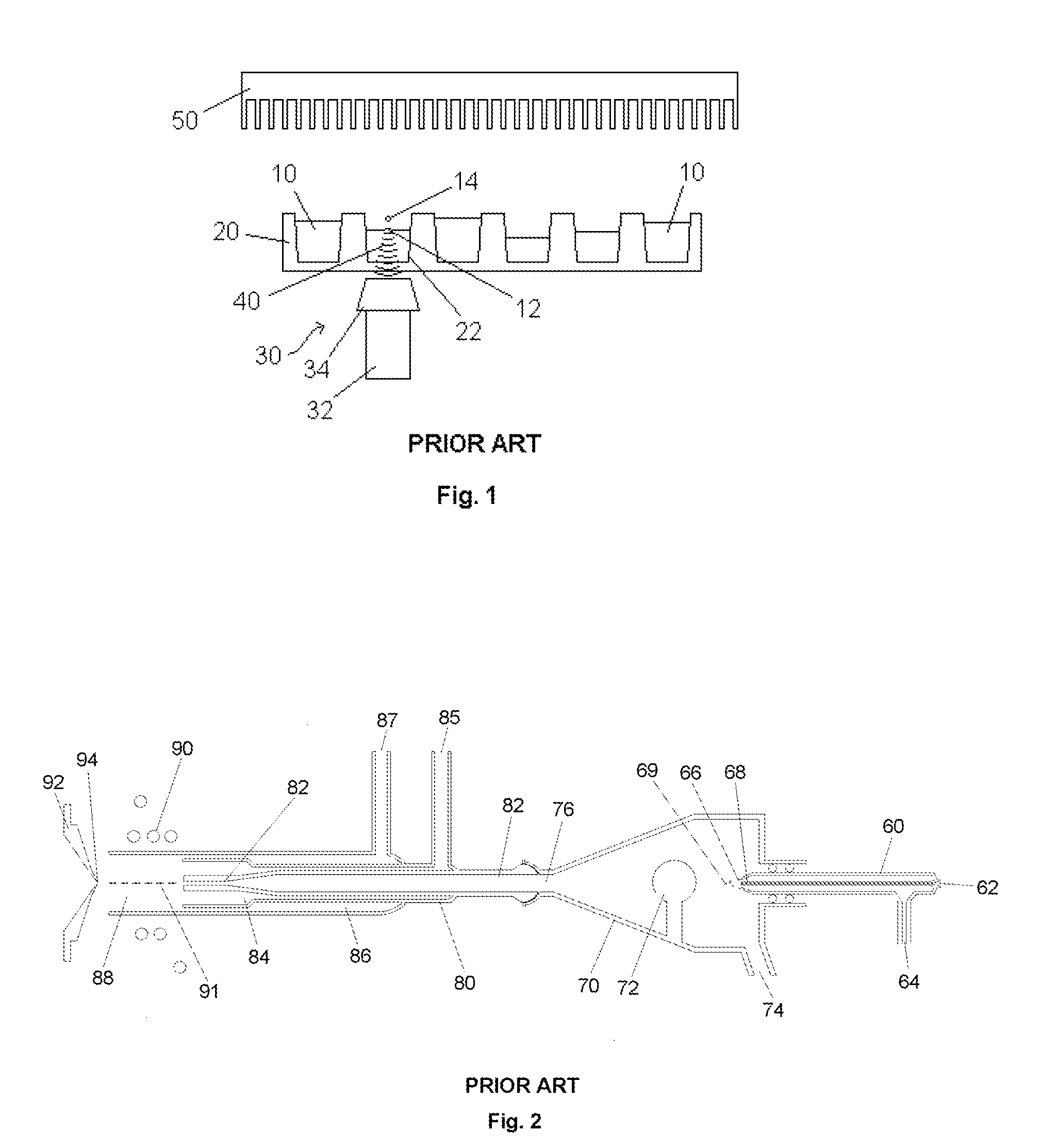
[0050]FIG. 1 is a schematic diagram of a prior art droplet ejection system utilizing an acoustic droplet ejector. Liquids to be dispensed, 10, are contained within an array of sample vessels, 20, in this case a well-plate. An acoustic transducer and lens system, 30, provides pulsed acoustic energy, 40, which travels from the acoustic transducer, 32, and through the incorporated lens system, 34, before being emitted to pass through the well-plate, 20, and into one of the vessels, 22. The lens system, 34, incorporated into the transducer and lens system 30 is arranged to focus the acoustic pulse on the surface region, 12, of the liquid within the vessel, 22. Upon arrival at the surface region, 12, the acoustic energy, 40, disrupts the surface of the liquid so as to eject a droplet, 14, of the liquid, 10. The droplet, 14 (not to scale), leaves the surface region, 12, and travels upward, approximately orthogonally away from the surface region 12, and is deposited on receiving plate 50, ...


PUM


Abstract

A method and apparatus for introducing droplets of liquid sample into an analysis device using a gas stream, the droplets being produced by the application of acoustic energy to a quantity of liquid sample. Acoustic energy may be applied to a quantity of liquid sample located on a solid surface of a sample support so as to eject a droplet of sample from the quantity of sample; the droplet of sample may be entrained in a gas stream; and the droplet of sample may be transported into the analysis device using the gas stream.

Description

FIELD OF THE INVENTION[0001]This invention relates to the field of liquid sample introduction systems for analytical instruments and relates to those analysis devices for which sample must be introduced in the form of a stream of droplets. The invention relates to a means for utilizing an acoustic droplet generator for producing droplets for direct injection into an analysis device.BACKGROUND[0002]Liquid sample supplied to an analysis device in the form of droplets is usually provided using a nebulizer to generate an aerosol. Analysis devices which utilize such droplets include ionization and / or excitation sources such as microwave induced plasma (MIP), inductively coupled plasma (ICP) and flames. The analysis devices provide spectrometers which perform MIP and ICP optical emission spectrometry (OES), MIP and ICP mass spectrometry (MS), atomic absorption spectrometry (AA) and atomic fluorescence spectroscopy (AFS). Typically the sample-containing liquid is formed into a stream of dr...

Claims


Application Information

Patent Timeline
IPC IPC(8): G01N35/10
CPCG01N2035/1034G01N35/10B01L3/0268B05B17/0615G01N1/38H01J49/0454B01L2300/0829B01L2400/0433G01N21/3103G01N21/6404B01J2/02B01J2/04B01J2/06G01N1/28G01N35/1095
Inventor HATTINGH, RUANBIRD, NEILNEAL, PAULMOTEAU, OLIVIERCLARK, ANDREW
Owner THERMO ELECTRON MFG
Why Eureka
Try Eureka