Euv-mirror arrangement, optical system with euv-mirror arrangement and associated operating method

Active Publication Date: 2014-09-25
CARL ZEISS SMT GMBH
View PDF5 Cites 21 Cited by
  • Summary
  • Abstract
  • Description
  • Claims
  • Application Information

AI Technical Summary

Benefits of technology

[0045]The layer thicknesses of the individual layers of the layer pairs and, if appropriate, also of the active layer are generally of the order of magnitude of a few nanometres. In order to minimize the influence of interface roughnesses on the optical effect of the mirror elements, in preferred embodiments provision is made for applying the active layer and/or possible electrode layers with the aid of pulsed laser deposition (PLD), such that the active layer and/or an electrode layer are/is present as a PLD layer. With the aid of pulsed laser deposition it is possible to produce very thin layers having little surface roughness. As necessary, it is also possible to produce monocrystalline piezoelectric layer materials having a high piezoelectric coefficient, the surface of which can then be used without polishing as a contact surface for further layers.
[0046]Preferably, at least that layer to which the active layer is applied is produced as a crystalline (non-amorphous) layer, in

Problems solved by technology

If it is attempted to improve the resolution by increasing the numerical aperture, then problems can arise by virtue of the fact that as the numerical aperture increases, the depth of focus (DOF) that can be achieved decreases.
This is disadvantageous because a depth of focus of the order of magnitude of at least 0.1 nm is desirable for example for reasons of the achievable flatness of the substrates to be structured and mechanical tolerances.
Radiation from the extreme ultraviolet range cannot be focus

Method used


Image

  • Euv-mirror arrangement, optical system with euv-mirror arrangement and associated operating method
  • Euv-mirror arrangement, optical system with euv-mirror arrangement and associated operating method
  • Euv-mirror arrangement, optical system with euv-mirror arrangement and associated operating method

Examples


Example

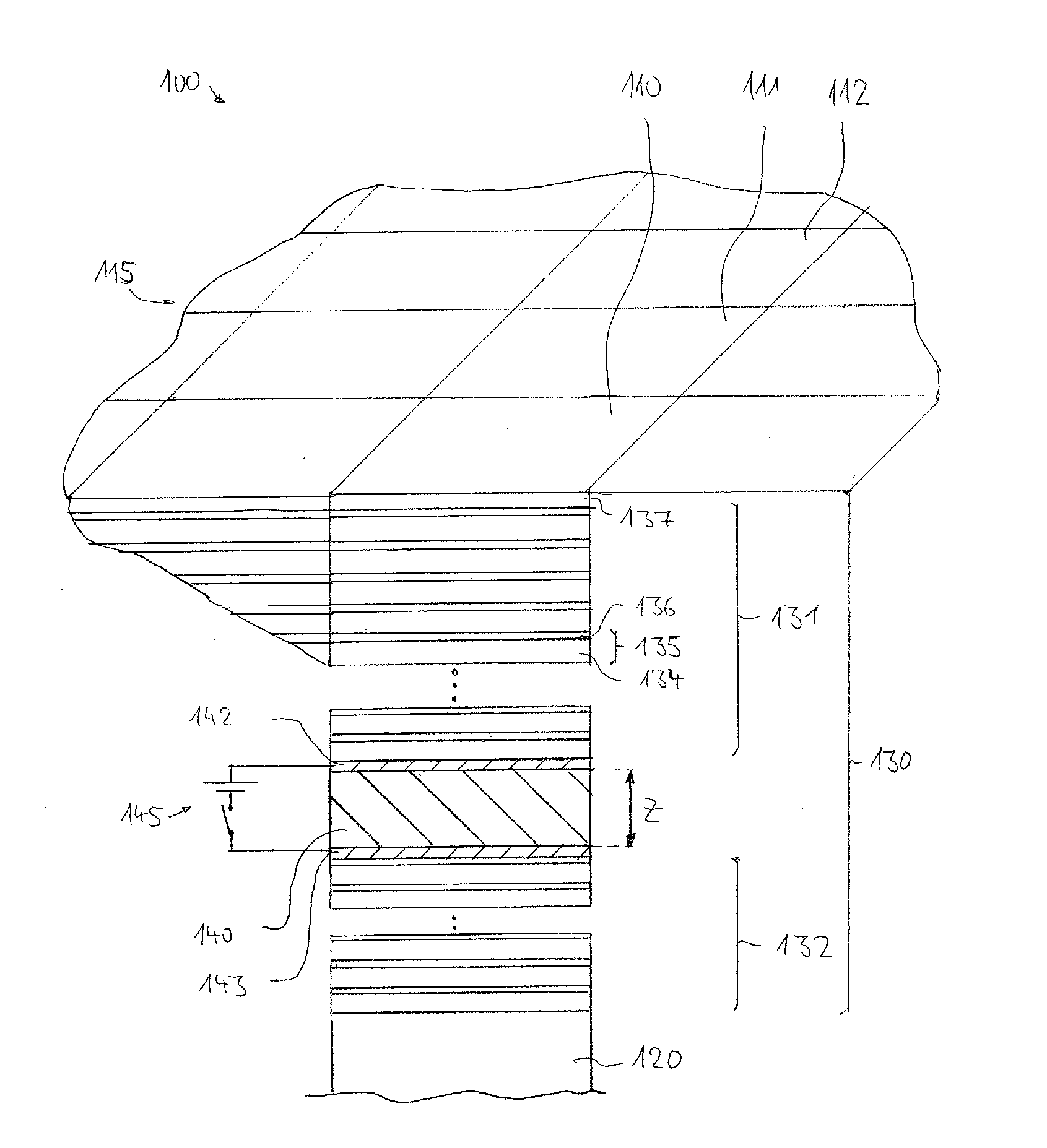
[0069]FIG. 1 shows a schematic, obliquely perspective illustration of an embodiment of an EUV mirror arrangement 100 in partial section. The mirror arrangement has a multiplicity of mirror elements 110, 111, 112 which are arranged alongside one another and which each have a rectangular cross section in the case of the example. Each mirror element can be designated as an individual mirror and has a rectangular element mirror surface, wherein the element mirror surfaces adjoin one another largely without any gaps or lie aside one another with interspaces and jointly form a mirror surface 115 of the mirror arrangement. The mirror surface can be flat (plane mirror) or curved (e.g. convex mirror, concave mirror, cylindrical mirror, etc.) overall.

[0070]The construction of a mirror element will be explained in greater detail on the basis of the mirror element 110. Each mirror element has a substrate 120, which can consist, for example, of metal, silicon, a glass, a ceramic material, a glas...


PUM


Abstract

An EUV mirror arrangement (100) has a multiplicity of mirror elements (110, 111, 112) which are arranged alongside one another and jointly form a mirror surface of the mirror arrangement. Each mirror element has a substrate (120) and a multilayer arrangement (130) applied on the substrate and having a reflective effect with respect to radiation from the extreme ultraviolet range (EUV), said multilayer arrangement comprising a multiplicity of layer pairs (135) having alternate layers composed of a high refractive index layer material and a low refractive index layer material. The multilayer arrangement has an active layer (140) arranged between a radiation entrance surface and the substrate and consisting of a piezoelectrically active layer material, the layer thickness (z) of which active layer can be altered by the action of an electric field. For each active layer provision is made of an electrode arrangement for generating an electric field acting on the active layer.

Description

[0001]The present application is a Continuation of International Application No. PCT / EP2012 / 055013, filed on Mar. 21, 2012, which claims priority of German Patent Application No. 10 2011 005 940.7, filed on Mar. 23, 2011, U.S. Provisional Application No. 61 / 466,631, filed on Mar. 23, 2011, German Patent Application No. 10 2011 077 234.0, filed on Jun. 8, 2011, and U.S. Provisional Application No. 61 / 494,718, filed on Jun. 8, 2011. The disclosures of these five applications are hereby incorporated herein by reference in their respective entireties.FIELD OF AND BACKGROUND OF THE INVENTION[0002]The invention relates to an EUV mirror arrangement in accordance with the preamble of claim 1, to an optical system comprising an EUV mirror arrangement in accordance with the preamble of claim 16, and to a method for operating an optical system in accordance with the preamble of claim 21. One preferred field of application is EUV microlithography. Other fields of application are in EUV microsco...

Claims


Application Information

Patent Timeline
IPC IPC(8): G03F7/20G02B5/08
CPCG02B5/0891G03F7/70166B82Y10/00G03F7/70075G03F7/702G21K1/062G21K2201/067G21K1/06
Inventor DINGER, UDOBIJKERK, FREDERIKBAYRAKTAR, MUHARREMDIER, OLIVER
Owner CARL ZEISS SMT GMBH
Why Eureka
Try Eureka