
Component having a micromechanical microphone structure

a microphone and micro-mechanical technology, applied in the direction of diaphragm construction, loudspeaker, electrostatic transducer, etc., can solve the problem of diaphragm structure bending, etc., to reduce the opening surface area and improve the damping properties of the microphone structur

Inactive Publication Date: 2014-10-02
ROBERT BOSCH GMBH
View PDF8 Cites 11 Cited by
  • Summary
  • Abstract
  • Description
  • Claims
  • Application Information

AI Technical Summary

Benefits of technology

The present invention provides options for achieving substrate-side overload protection for the diaphragm structure of a microphone component of the type mentioned at the outset which impair the damping properties of the microphone structure as little as possible. The invention uses the edge area of the sound opening as a substrate-side stop without significantly reducing the opening surface area of the sound opening in comparison to the diaphragm surface area. The invention includes projections that are easily structured from the diaphragm layer without additional manufacturing effort and are coordinated with the size and shape of the component. The invention also includes connecting elements that counteract a bending of the projections without impairing the diaphragm sensitivity and assist in protecting and stabilizing the individual projections. The invention further includes bar-like structural elements that are so narrow that they do not significantly reduce the opening surface area of the sound opening and are easily produced together with the sound opening in the substrate by an appropriate masking process.

Problems solved by technology

However, this may prove to be problematic in practice, since manufacturing-related mechanical stresses occur in the very thin diaphragm structure which result in bending of the diaphragm structure.

Method used


Image

  • Component having a micromechanical microphone structure
  • Component having a micromechanical microphone structure
  • Component having a micromechanical microphone structure

Examples


Embodiment Construction

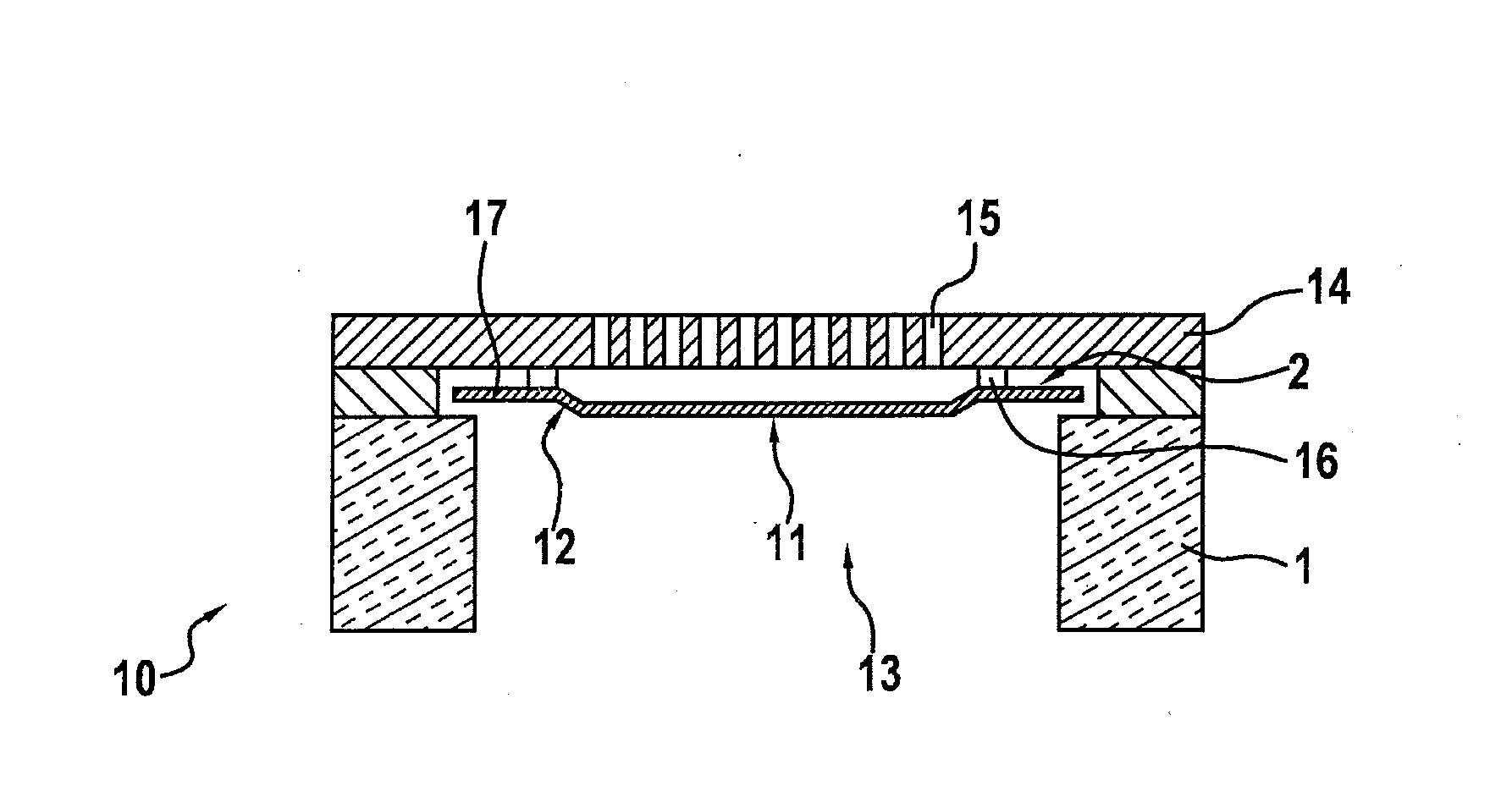
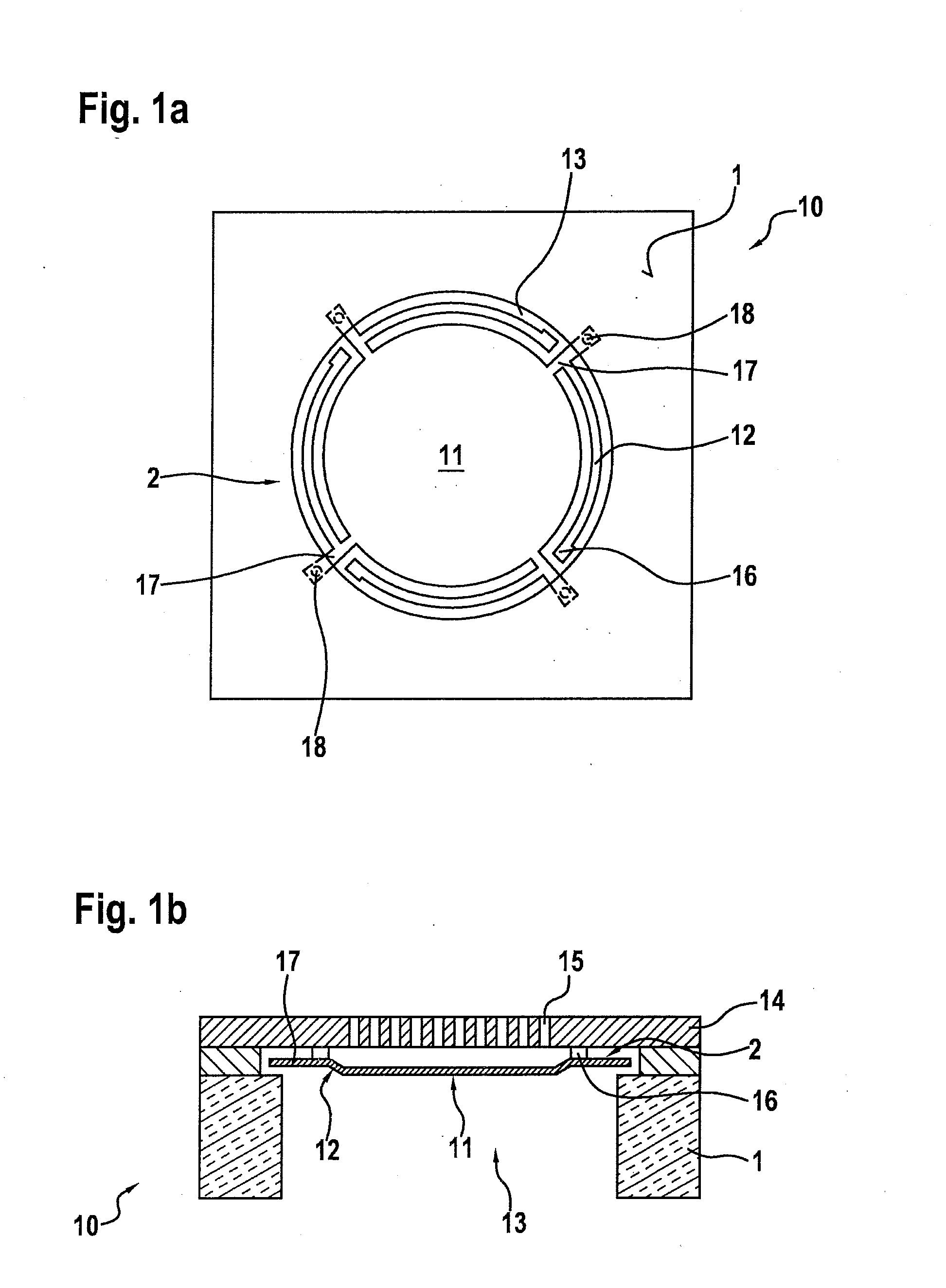
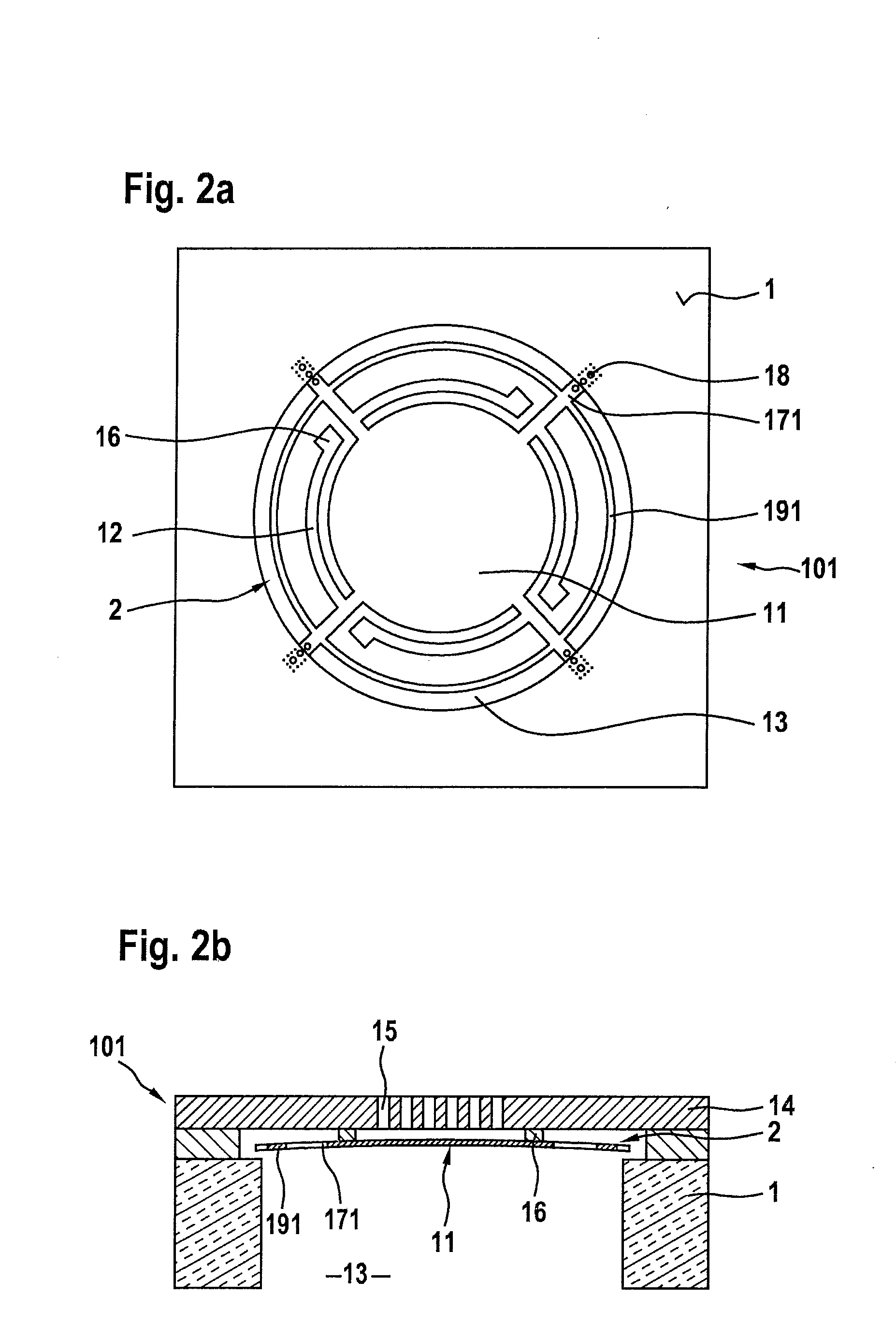
[0025]The microphone structure of MEMS microphone component 10 illustrated in FIGS. 1a and 1b is implemented in a layer structure on a semiconductor substrate 1. The microphone structure includes a diaphragm structure 2 having an acoustically active diaphragm 11 which in the exemplary embodiment described here is circular, and which acts as the deflectable electrode of a microphone capacitor. The microphone structure is integrated into the layer structure of component 10 via four spring elements 12. FIG. 1a shows the layout of diaphragm structure 2, while FIG. 1b illustrates the layer structure of component 10.

[0026]Overall diaphragm structure 2 is formed in a relatively thin diaphragm layer above semiconductor substrate 1, which may be composed of one or also multiple material layers. Accordingly, spring elements 12 are made of the same material as diaphragm 11. The layout of the spring suspension, i.e., the number, configuration, and shape of spring elements 12, has been selected ...


PUM


Abstract

Substrate-side overload protection for the diaphragm structure of a microphone component having a micromechanical microphone structure which impairs the damping properties of the microphone structure as little as possible, in which the microphone structure includes a diaphragm structure having at least one acoustically active diaphragm which is formed in a diaphragm layer above a semiconductor substrate. The diaphragm structure spans at least one sound opening in the rear side of the substrate. A stationary, acoustically permeable counter element is formed in the layer structure of the component above the diaphragm layer. According to the invention, at least projections are formed at the outer edge area of the diaphragm structure which protrude beyond the edge area of the sound opening, so that the edge area of the sound opening acts as a substrate-side stop for the diaphragm structure.

Description

FIELD OF THE INVENTION[0001]The present invention relates to a component having a micromechanical microphone structure which is implemented in a layer structure on a semiconductor substrate. The microphone structure includes a diaphragm structure having an acoustically active diaphragm, the diaphragm structure being formed in a diaphragm layer above the semiconductor substrate and spanning at least one sound opening in the rear side of the substrate. In addition, the microphone structure includes a stationary, acoustically permeable counter element which is formed in the layer structure above the diaphragm layer, and substrate-side overload protection for the diaphragm structure.BACKGROUND INFORMATION[0002]Structural elements such as spring elements are frequently formed in the edge area of a microphone diaphragm, via which the diaphragm is integrated into the layer structure of the component. On the one hand, this type of suspension has the function of absorbing manufacturing- and ...

Claims


Application Information

Patent Timeline
IPC IPC(8): H04R7/06H04R19/00H04R19/04
CPCH04R19/04B81B3/0051H04R2201/003H04R7/06H04R19/005B81B2201/0257
Inventor ZOELLIN, JOCHENLAERMER, FRANZSCHELLING, CHRISTOPHDALEY, MIKE
Owner ROBERT BOSCH GMBH
Learn More