
Weld metal having excellent temper embrittlement resistance

Inactive Publication Date: 2014-10-02
KOBE STEEL LTD
View PDF1 Cites 2 Cited by
  • Summary
  • Abstract
  • Description
  • Claims
  • Application Information

AI Technical Summary

Benefits of technology

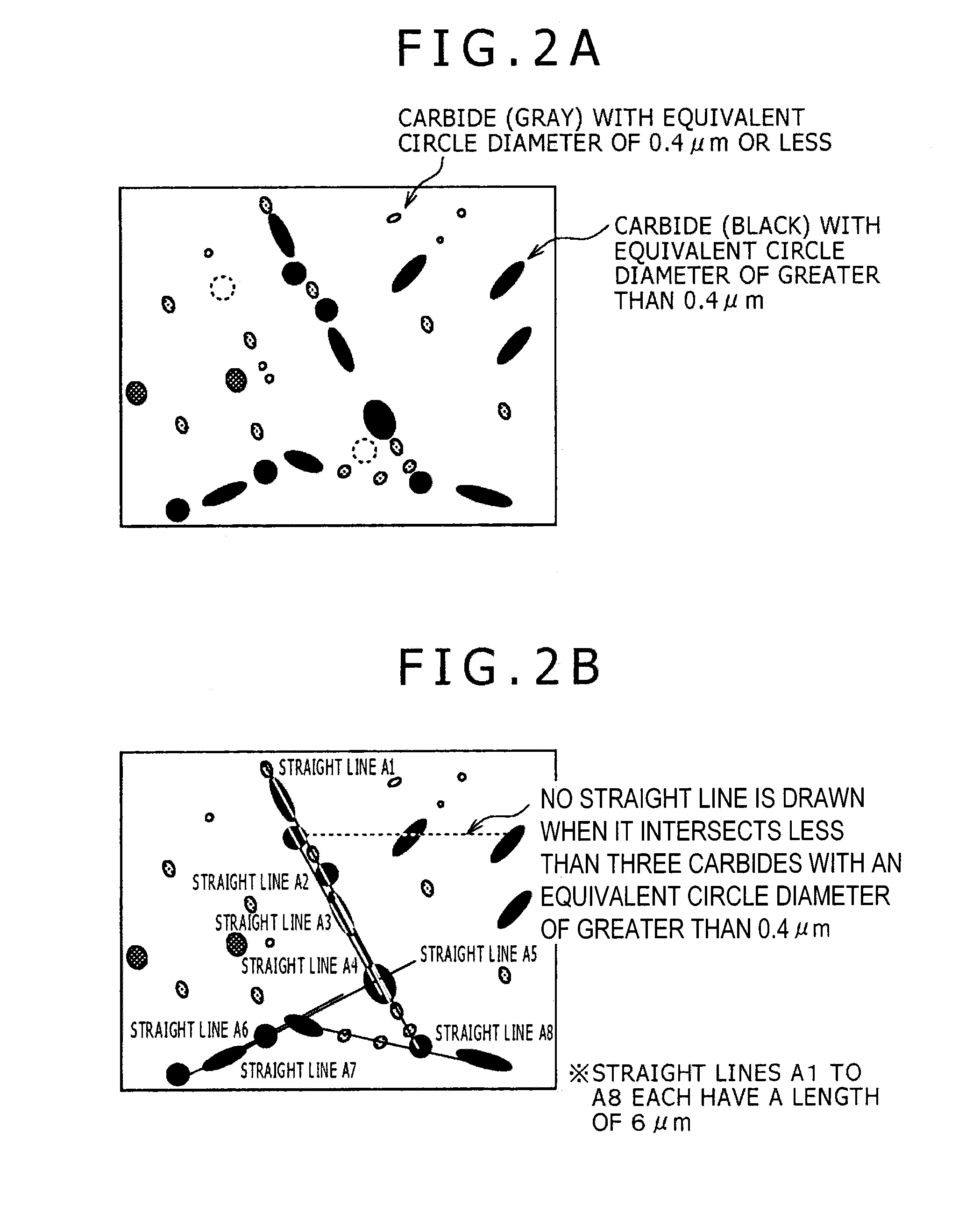
The present invention is about improving the quality of weld metal by controlling its chemical composition and the size of carbide particles present at grain boundaries. This results in weld metal that is resistant to temper embrittlement and has good toughness, stress-relief cracking resistance, and strength. Furthermore, the invention suppresses the presence of coarse oxide particles, which enhances the toughness of the weld metal after an SR heat treatment and even after temper embrittlement treatment.

Problems solved by technology

Such increasing welding heat input will generally cause weld beads to have a coarsened microstructure and inferior toughness (inferior temper embrittlement resistance).
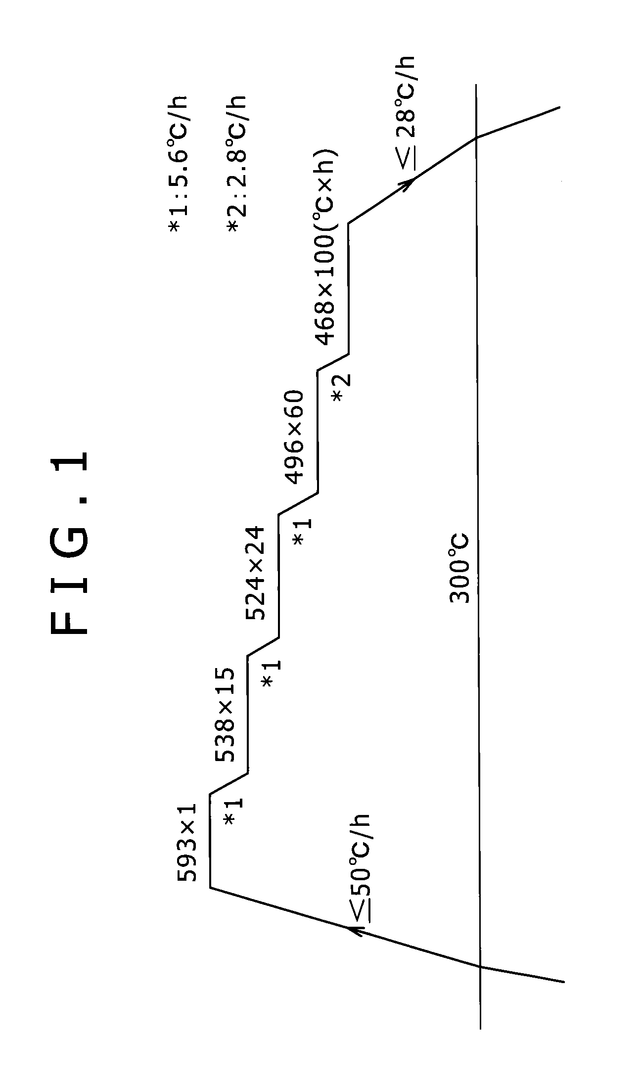
Some working examples according to this technique, however, have unsatisfactory toughness after a temper embrittling treatment (step cooling) in terms of vTr′5.5 of at best −41° C., although having satisfactory toughness after a stress relief heat treatment (SR heat treatment) in terms of vTr5.5 of −50° C. The term “vTr′5.5” refers to a temperature at which a sample after the step cooling has an absorbed energy of 5.5 kgf·m.
The technique, however, fails to give consideration to temper embrittlement resistance.
This indicates that the techniques fail to sufficiently suppress temper embrittlement.
The technique, however, fails to give consideration to temper embrittlement resistance.
In addition, the technique is significantly limited in operation because a designed welding heat input is small.
In view of recommended welding conditions, however, the techniques fail to sufficiently support increase in welding heat inputs.

Method used


Image

  • Weld metal having excellent temper embrittlement resistance
  • Weld metal having excellent temper embrittlement resistance
  • Weld metal having excellent temper embrittlement resistance

Examples


examples

[0065]The present invention will be illustrated in further detail with reference to several examples below. It should be noted, however, that the examples are never construed to limit the scope of the invention; that various changes and modifications are possible within purview of the description as described above and below; and that it is intended to cover all such changes and modifications as fall within the true spirit and scope of the invention.

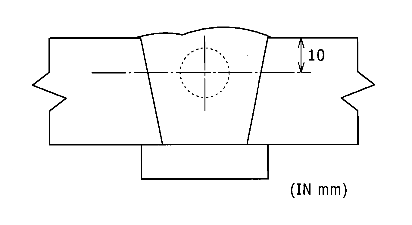
[0066]Weld metals were prepared using a base metal having a chemical composition under welding conditions mentioned later, subjected to a heat treatment, and evaluated on various properties.

Base Metal Chemical Composition (Percent by Mass)

[0067]C in a content of 0.12%; Si in a content of 0.23%; Mn in a content of 0.48%; P in a content of 0.004%; S in a content of 0.005%; Cu in a content of 0.04%; Al in a content of less than 0.002%; Ni in a content of 0.08%; Cr in a content of 2.25%; Mo in a content of 0.99%; V in a content of 0.004%; Ti...


PUM

PropertyMeasurementUnit
Lengthaaaaaaaaaa
Fractionaaaaaaaaaa
Fractionaaaaaaaaaa

Abstract

A weld metal according to the present invention has a specific chemical composition, contains carbide particles each having an equivalent circle diameter of greater than 0.5 μm in a number of 0.25 or less per micrometer of grain boundary length, and has an A-value as specified by Formula (1) of 0.12 or more, Formula (1) expressed as follows:A-value=([V] / 51+[Nb] / 93) / ([Cr] / 52+[Mo] / 96)   (1)where [V], [Nb], [Cr], and [Mo] are contents (percent by mass) of V, Nb, Cr, and Mo, respectively, in the weld metal.

Description

TECHNICAL FIELD [0001]The present invention generally relates to weld metals for use in welding of high-strength steels such as Cr—Mo steels. Specifically, it relates to a weld metal having better temper embrittlement resistance; and a welded structure including the weld metal.BACKGROUND ART[0002]High-strength Cr—Mo steels and weld beads (weld metals) thereof for use in steam boilers and chemical reactors are exposed to a high-temperature and high-pressure environment during use. They require not only basic properties such as strength and toughness, but also heat resistance (high-temperature strength), stress-relief cracking resistance [resistance to intergranular cracking during a stress-relief heat treatment (SR heat treatment)], and temper embrittlement resistance (resistance to embrittlement during use in a high-temperature environment) at high levels. Recent apparatuses have larger sizes and larger wall thicknesses. Welding on these large-sized apparatuses has been performed wi...

Claims


Application Information

Patent Timeline
IPC IPC(8): B23K35/30
CPCB23K35/3086B23K9/23B23K35/365C21D9/50C22C38/001C22C38/002C22C38/02C22C38/04C22C38/06C22C38/20C22C38/22C22C38/24C22C38/26C22C38/32C22C38/34C22C38/38C22C38/42C22C38/44C22C38/46C22C38/48B23K2103/04B23K35/30C22C38/54B23K35/3053B23K35/3093B23K35/308B23K35/3602C22C38/50B23K35/0261B23K35/0266
Inventor NAKO, HIDENORIYAMASHITA, KENOTSU, MINORUTANIGUCHI, GENICHISAKATA, MIKIHIRO
Owner KOBE STEEL LTD
Learn More