Banking structure using rocks producing acid drainage

a technology of acid drainage and bank structure, applied in the field of bank structure, can solve the problems of reduced ground stability, large-scale underground excavation, corrosion of structures, etc., and achieve the effect of improving performan

Active Publication Date: 2014-10-02
KOREA INST OF GEOSCI & MINERAL RESOURCES
View PDF10 Cites 7 Cited by
  • Summary
  • Abstract
  • Description
  • Claims
  • Application Information

AI Technical Summary

Benefits of technology

[0009]The present invention provide a banking structure having improved performance to recycle rocks producing acid drainage into banking materials so that the acid drainage does not have an influence on the surrounding soil, river, and underground water.

Problems solved by technology

However, if the iron pyrites are exposed to the surface of the earth by underground excavation, drainage, dredge, and the like, the iron pyrites meet oxygen and thus are oxidized to produce acid drainage.
In recent years, large scale underground excavation frequently occurs due to road building and residential land and industrial complex development.
Rocks containing the sulfide minerals exposed to the surface of the earth during the underground excavation may produce the acid drainage to cause various problems such as environmental pollution, corrosion of structures, vegetation withering, scenery damage, rock weathering promotion, reduction of ground stability, and the like.
However, the construction method may be complicated, and a relatively large amount of cost and time may be required.
Also, the perforated drainpipe and waterproof sheet may be frequently damaged when constructed and thus deteriorated in effectiveness.
Also, due to leakage of aggregate, needs for recycling the excavated rocks into banking materials are increasing.
Thus, although there is an attempt to recycle the rocks into the banking materials, a technique for solving problem of all sorts due to the oxidation of the sulfide minerals within the rocks through penetration of rainwater and the contact with air has not been proposed.
Thus, the industrial recycling of the rocks is investigated only negative attention.

Method used


Image

  • Banking structure using rocks producing acid drainage
  • Banking structure using rocks producing acid drainage
  • Banking structure using rocks producing acid drainage

Examples


Embodiment Construction

[0028]Hereinafter, a banking structure using rocks producing acid drainage according to a first embodiment of the present invention will be described in detail with reference to the accompanying drawings.

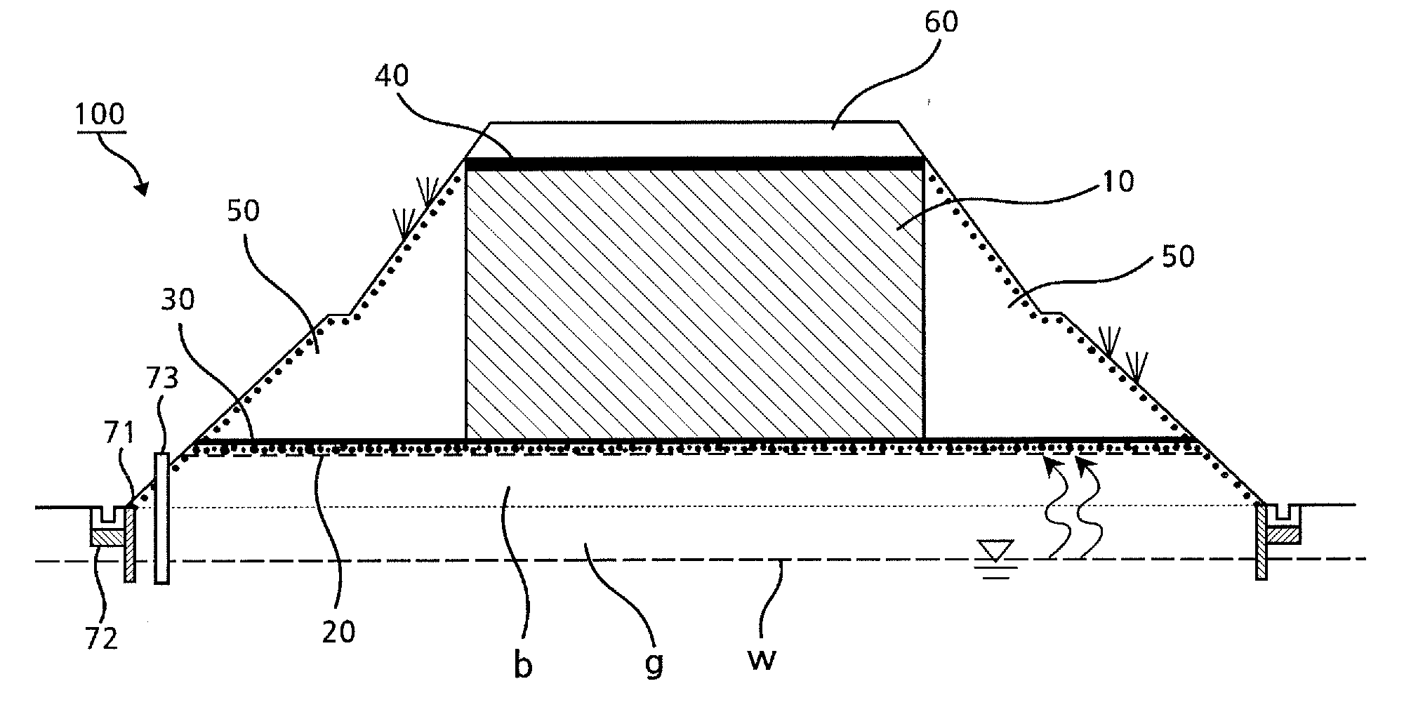
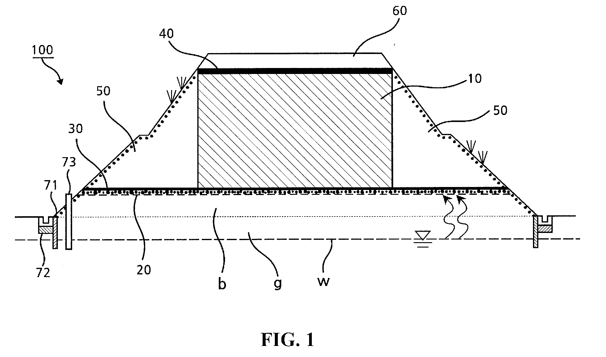
[0029]FIG. 1 is a schematic cross-sectional view of a banking structure according to a first embodiment of the present invention.

[0030]Referring to FIG. 1, a banking structure 100 according to the first embodiment of the present invention includes a banking layer 10, a capillary breaker layer 20, a lower blocking layer 30, an upper blocking layer 40, and a cover layer 50.

[0031]The banking structure 100 according to the first embodiment is constructed in order of the capillary breaker layer 20, the lower blocking layer 30, the banking layer 10, the upper blocking layer 40, and the cover layer 50. However, for convenience of description, the banking layer 10 will be described first.

[0032]The banking layer 10 may be a layer that is formed by mixing the rocks producing the acid drainage...


PUM


Abstract

Provided is a banking structure using a rock producing acid drainage. The banking structure includes a banking layer including the rock having acid drainage production possibility and an inhibitor for reducing acid drainage production potential of the rock, a capillary breaker layer stacked between a lower portion of the banking layer and an underground water level surface to prevent underground water from being introduced into the banking layer by a capillary phenomenon, and a finishing layer stacked on an upper portion of the banking layer according to a use thereof.

Description

CROSS-REFERENCE TO RELATED APPLICATIONS[0001]This U.S. non-provisional patent application claims priority under 35 U.S.C. §119 of Korean Patent Application No. 10-2013-0035567, filed on Apr. 2, 2013, the entire contents of which are hereby incorporated by reference.BACKGROUND OF THE INVENTION[0002]The present invention relates to a banking technique in civil engineering and construction fields, and more particularly, a banking structure using rocks producing acid drainage as backing materials.[0003]Sulfide minerals may be minerals that are commonly produced from rocks and sediments. The sulfide minerals may be produced by various geological processes such as diagenesis of sediments deposited under reducing environments, deposition from hot water, and reaction between hot water and rocks. Sulfide minerals may be produced from various kinds of rocks according to generation environments. Iron pyrites may be the most representative sulfide minerals.[0004]In case of the iron pyrites, the...

Claims


Application Information

Patent Timeline
Patent Type & Authority Applications(United States)
IPC IPC(8): B09C1/08
CPCB09C1/08E02D3/12E01C1/00E02D17/18E02D29/02
Inventor KIM, JAE GONSONG, YOUNG SUKCHON, CHUL MINNAM, IN HYUNLEE, JIN SOO
Owner KOREA INST OF GEOSCI & MINERAL RESOURCES
Why Eureka
Try Eureka