
Tool head and method for machining a metallic workpiece

Active Publication Date: 2014-10-02
KENNAMETAL INC
View PDF20 Cites 4 Cited by
  • Summary
  • Abstract
  • Description
  • Claims
  • Application Information

AI Technical Summary

Benefits of technology

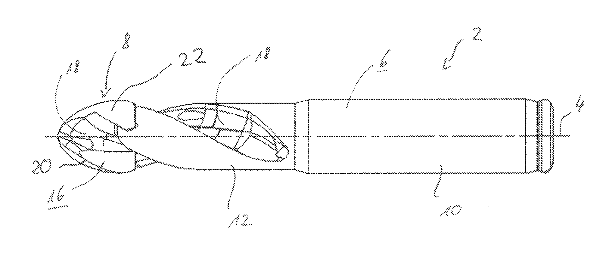
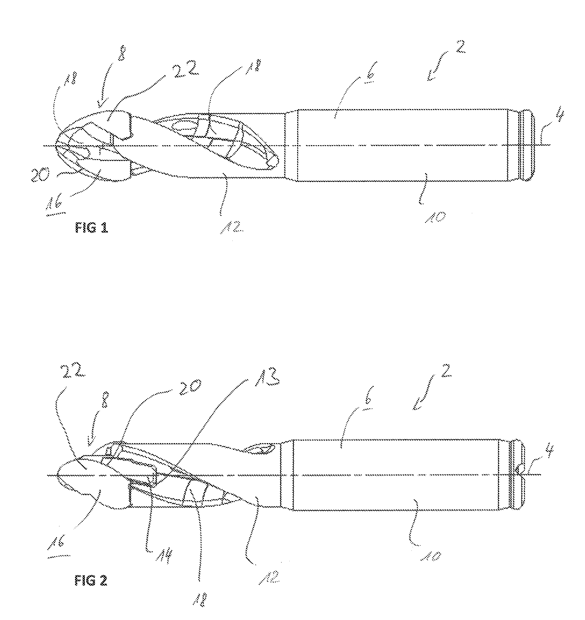
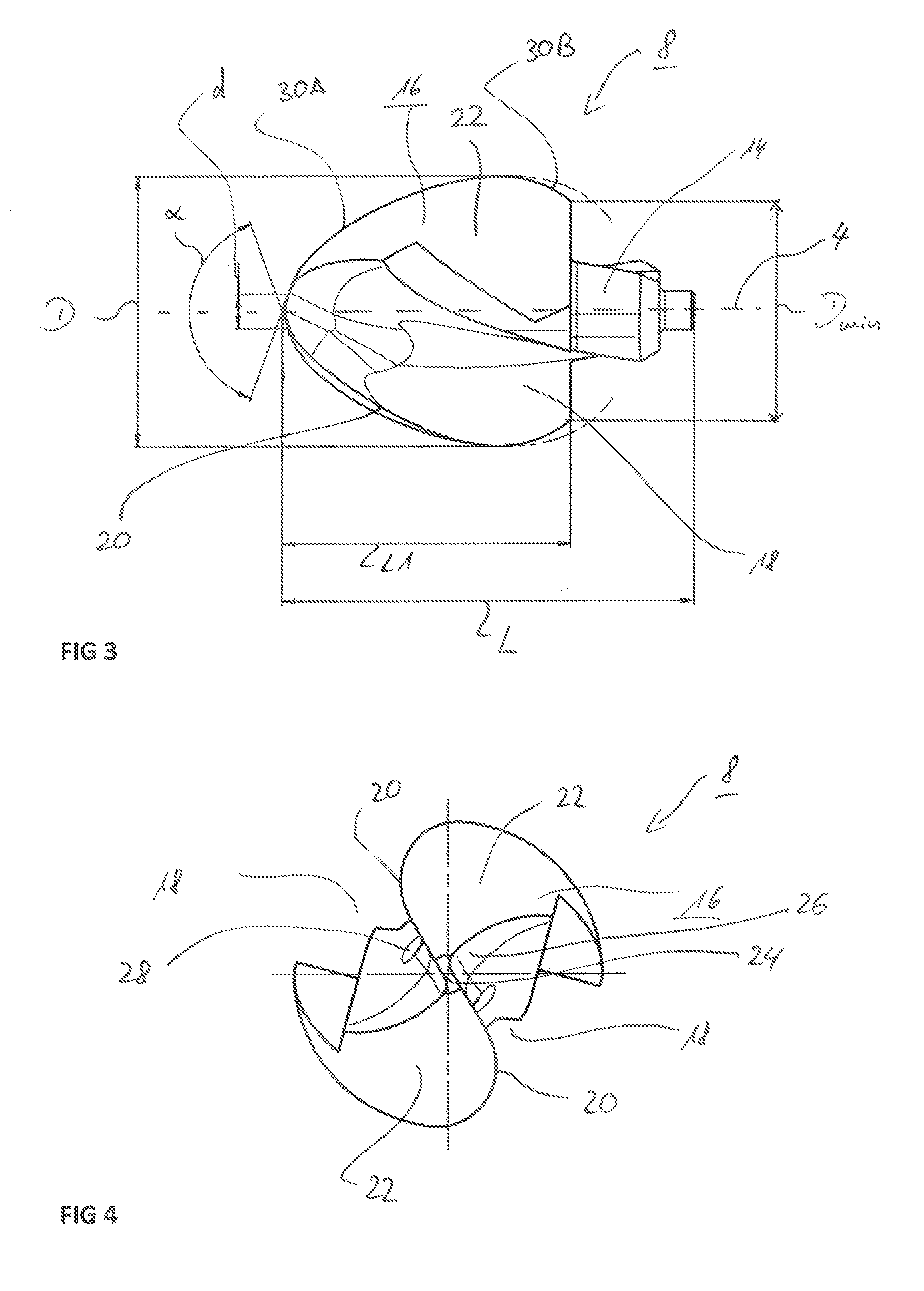
This invention is a tool head, specifically a drilling head, that is designed for machining hard materials such as titanium or cast materials. By using an ovoid shape, the forces from cutting are transmitted and conducted along the surface of the drilling head in a way that reduces the load on the cutting edges. This results in faster cutting speeds and improved efficiency compared to traditional drilling tools. The rear arc portion of the drilling head is curved more strongly than the front arc portion, which reduces the axial length and keeps the cutting load low overall. The individual arc portions are composed of segments with different radii, allowing for better force transmission and lower cutting load. The tool head with the ovoid shape can achieve significantly higher cutting speeds and machining rates compared to traditional tools.

Problems solved by technology

In machine cutting, in particular in the drilling of hard materials, there is generally the problem of high load upon the cutting edges of the tool head.
This usually has the result that only comparatively low machining rates can be set and / or a high level of wear occurs.
The generated forces also occasionally lead under adverse conditions to chipping of the cutting edges.
Such problems arise in particular, for instance, in the aviation sector, in which very hard metallic materials, for instance titanium, are used.
In the case of the material titanium, there is the particular problem that the chips tend to adhere or stick to the cutting edge.
Succeeding cuttings can then lead to a locally very high load upon the cutting edge, so that the risk of chipping is high.
Moreover, high loads also arise in respect of cast materials, for instance gray cast iron, in particular due to an inhomogeneous material structure.

Method used


Image

  • Tool head and method for machining a metallic workpiece
  • Tool head and method for machining a metallic workpiece
  • Tool head and method for machining a metallic workpiece

Examples


Embodiment Construction

[0035]The foregoing has broadly outlined features and technical advantages of the present disclosure in order that the detailed description of the disclosure that follows may be better understood. Additional features and advantages of the disclosure will be described hereinafter which form the subject of the claims of the disclosure. It should be appreciated by those skilled in the art that the conception and specific embodiments disclosed may be readily utilized as a basis for modifying or designing other structures for carrying out the same purposes of the present disclosure. It should also be realized by those skilled in the art that such equivalent constructions do not depart from the spirit and scope of the disclosure as set forth in the appended claims. The novel features which are believed to be characteristic of the disclosure, both as to its organization and method of operation, together with further objects and advantages will be better understood from the following descri...


PUM

PropertyMeasurementUnit
Speedaaaaaaaaaa
Lengthaaaaaaaaaa
Diameteraaaaaaaaaa

Abstract

A tool head includes an ovoid basic element disposed about a center axis, at least two chip grooves formed in the basic element, and a number of major cutting edges. Each major cutting edge is disposed in a convex course along a respective chip groove of the at least two chip grooves. The major cutting edges define with their radially outermost region a nominal diameter. A radial distance from each major cutting edge to the center axis in a front, tip-side, arc portion increases up to the nominal diameter and in a rear, shank-side, arc portion decreases back down to a minimum diameter.

Description

BACKGROUND[0001]1. Field of the Invention[0002]Embodiments of the present invention relate to a tool head, in particular to a drilling head for machining a metallic workpiece, wherein the tool head has a center axis and at least two major cutting edges, which, viewed in a side view, take a convex course and define with their radially outermost region a nominal radius. Embodiments of the present invention further relate to a method for machining a metallic workpiece with a tool bearing such a tool head.[0003]2. Background Information[0004]In machine cutting, in particular in the drilling of hard materials, there is generally the problem of high load upon the cutting edges of the tool head. This usually has the result that only comparatively low machining rates can be set and / or a high level of wear occurs. The generated forces also occasionally lead under adverse conditions to chipping of the cutting edges.[0005]Such problems arise in particular, for instance, in the aviation sector,...

Claims


Application Information

Patent Timeline
IPC IPC(8): B23B51/02
CPCB23B51/02B23B2251/408B23B2251/24B23B2251/082B23B2251/02B23B2222/88B23B2251/18B23B2251/248Y10T408/03Y10T408/9098Y10T408/9097Y10T408/909
Inventor HIRT, MARKUSSHERIF, TAMIR PATRIC
Owner KENNAMETAL INC
Learn More