Active adaptive hydraulic ripple cancellation algorithm and system

Inactive Publication Date: 2014-10-02
CLEARMOTION INC
View PDF9 Cites 25 Cited by
  • Summary
  • Abstract
  • Description
  • Claims
  • Application Information

AI Technical Summary

Benefits of technology

The invention relates to a device and method to electronically control and improve the ripple characteristics of hydraulic pumps and motors. The device uses an electric motor to control the torque applied to the hydraulic pump, which results in the generation of pressure differential. The pressure differential fluctuates with the rotational position of the pump, and a ripple torque is applied to attenuate these fluctuations. The ripple torque is commanded by a ripple model that takes into account the rotor position, motor torque, hydraulic flow rate, and hydraulic pressure. The ripple model can be adaptable and updated based on sensor input. The technical effects of the invention include improved control over motor torque, reduced power loss, improved ripple torque cancellation, and reduced noise in the hydraulic pump.

Problems solved by technology

Typically in positive displacement hydraulic pumps / motors pressure differential generated by constant torque application contains pressure ripple that is largely undesirable.
This ripple is typically the result of non-constant flow capacity of the hydraulic pump / motor and of the variable leakage path around the pump / motor as a function of the position.
These arrangements require a second flow control source (e.g. the piston) in order to function, resulting in a complex system with multiple electronically controlled devices.
This arrangement also requires direct measurements of the flow or pressure ripple to perform closed loop feedback control of the secondary flow source, resulting in a more expensive system.
This arrangement also has the negative attribute of requiring multiple independently controlled hydraulic flow generating devices.
In this manner the additional electric power losses associated with this method of ripple cancellation are a result of the electrical resistance losses due to the difference between the root mean square current and the mean current required to produce the tipple current.
Pressure differential generated across the hydraulic pump results in a force on the piston of the actuator.

Method used


Image

  • Active adaptive hydraulic ripple cancellation algorithm and system
  • Active adaptive hydraulic ripple cancellation algorithm and system
  • Active adaptive hydraulic ripple cancellation algorithm and system

Examples


Embodiment Construction

[0031]Some aspects relate to a system and feed-forward control method of electronically attenuating pressure ripple in a positive displacement pump / motor. Other aspects relate to a method of adapting a model based feed-forward control on the basis of output sensor information.

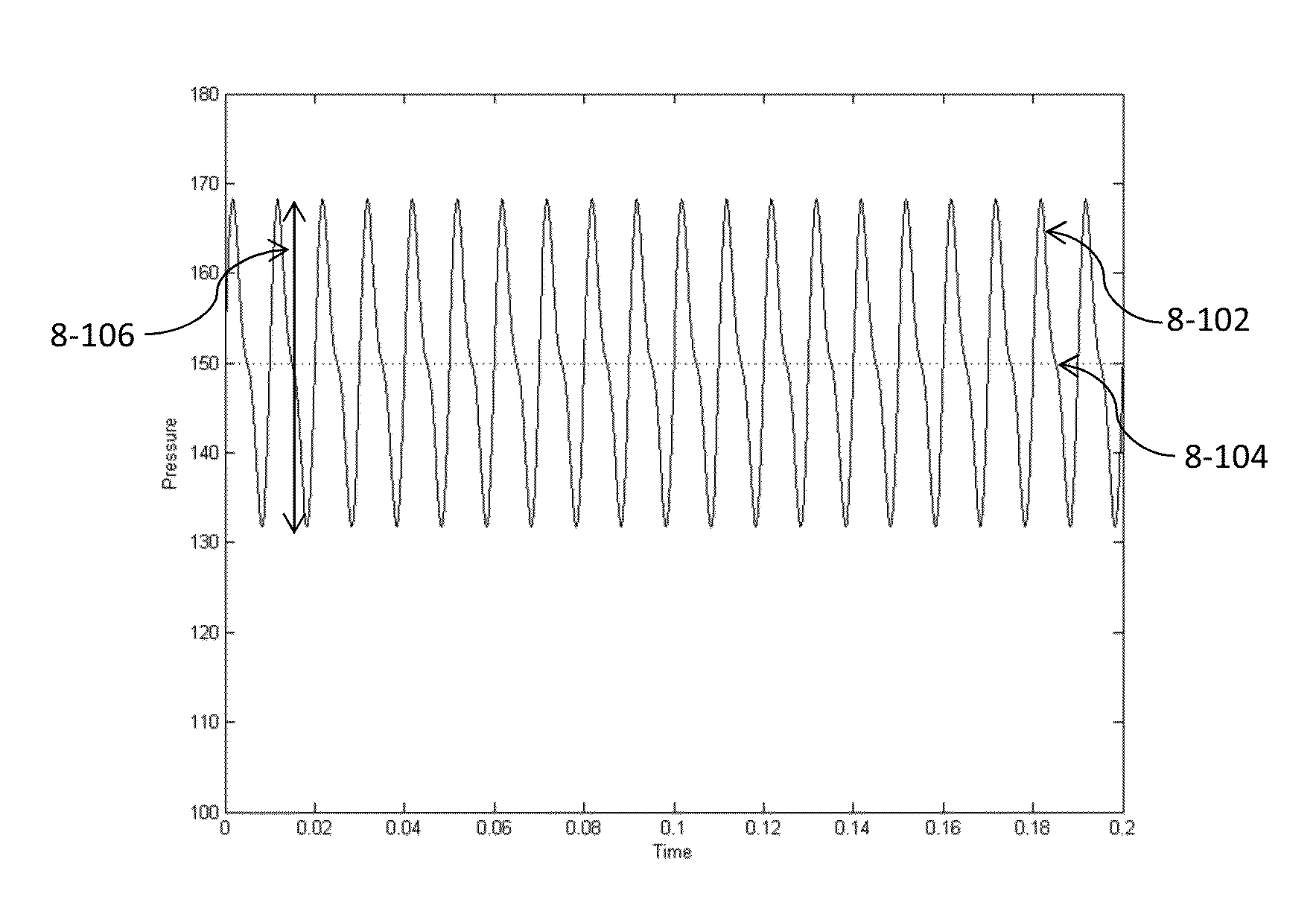
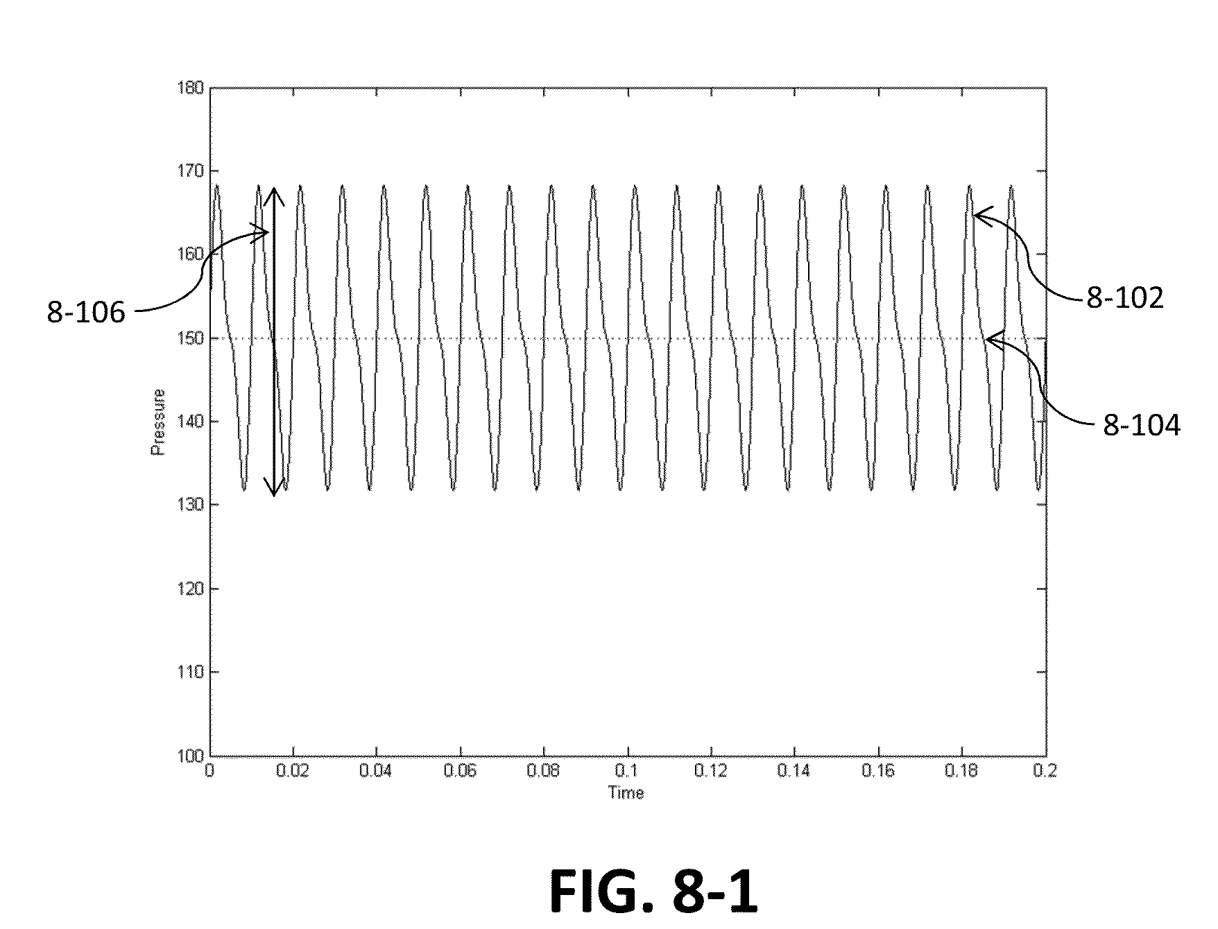
[0032]Regarding FIG. 8-1, a representative plot of steady state pressure ripple in the time domain is shown for a hydraulic pump / motor operating at constant frequency under a constant torque application. A generated pressure differential signal 8-102 fluctuates in time about a mean pressure differential 8-104 which is substantially constant throughout time. The peak-to-peak amplitude 8-106 of this fluctuating pressure differential signal 8-102 is substantially consistent throughout time as the geometric pattern of the hydraulic pump / motor is symmetric. The peak-to-peak amplitude 8-106 is determined by many characteristics of the hydraulic pump.

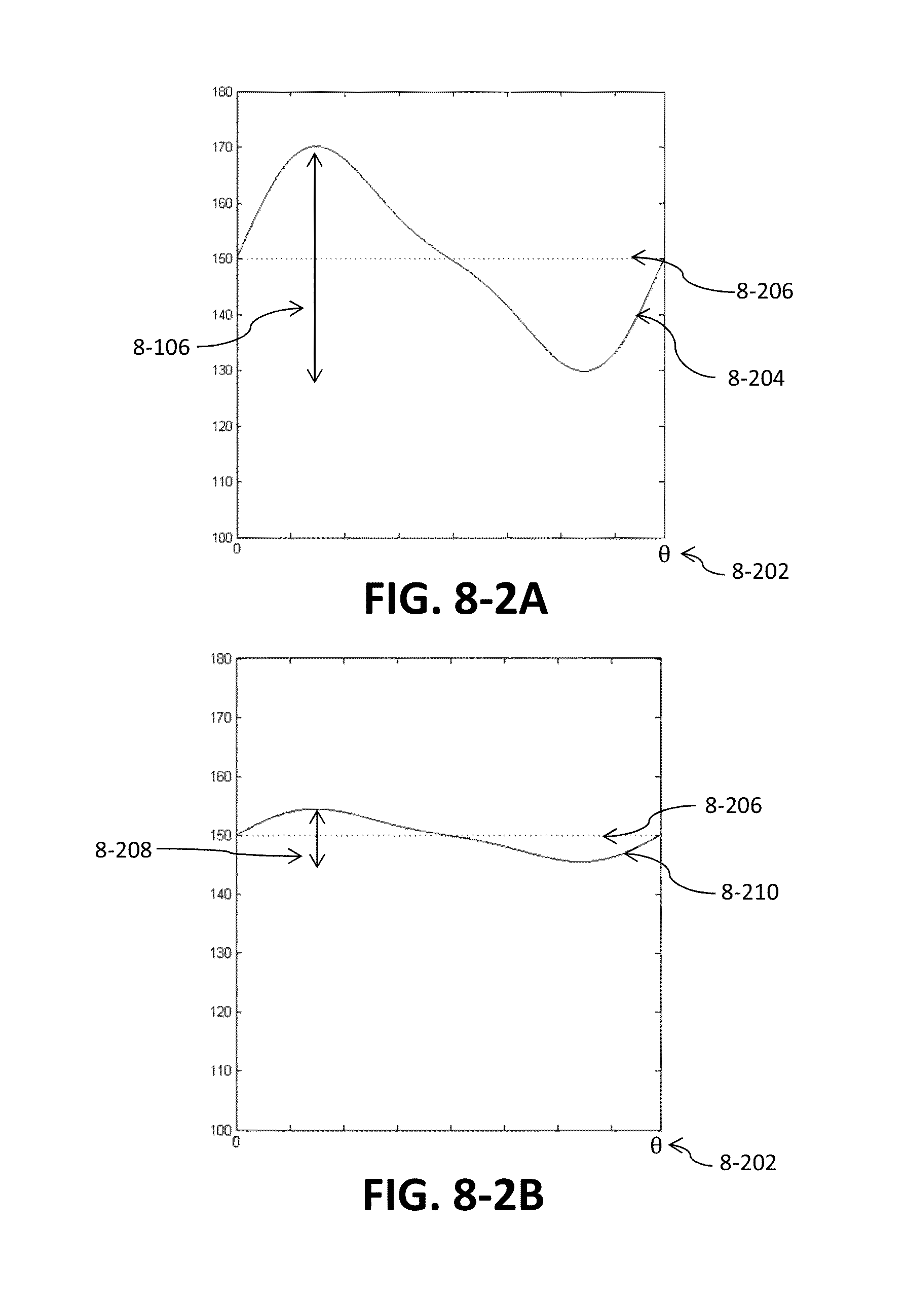
[0033]In FIG. 8-2A a representative plot of steady state pressure ri...


PUM


Abstract

Hydraulic pumps / motors are used to convert between rotational motion / power and fluid motion / power. Pressure differential is achieved across the pump / motor by applying torque to either aid or impede rotation which generally results in either a pressure rise or pressure drop respectively across the unit. This torque is often supplied by an electric motor / generator. Especially in positive displacement pumps / motors this pressure differential is not a smooth value but rather it contains high frequency fluctuations known as pressure ripple that are largely undesirable. With thorough analysis it can be discovered that these fluctuations occur in a predictable manner with respect to the position (angular or linear) of the pump / motor. Using a model that contains this information, a feed-forward method of high-frequency motor torque control is implemented directly on the hydraulic pump / motor by adding to the nominal torque, a model-based torque signal that is linked to rotor position. This high-frequency signal acts directly on the hydraulic pump / motor to reduce or cancel the pressure / flow ripple of the pump / motor itself without the need for any secondary flow generating devices.

Description

CROSS-REFERENCE TO RELATED APPLICATIONS[0001]This application claims priority to PCT application serial number PCT / US2014 / 029654, entitled “ACTIVE VEHICLE SUSPENSION IMPROVEMENTS”, filed Mar. 14, 2014, which claims the priority under 35 U.S.C. §119(e) of U.S. provisional application Ser. No. 61 / 913,644, entitled “WIDE BAND HYDRAULIC RIPPLE NOISE BUFFER”, filed Dec. 9, 2013, U.S. provisional application Ser. No. 61 / 865,970, entitled “MULTI-PATH FLUID DIVERTER VALVE”, filed Aug. 14, 2013, U.S. provisional application Ser. No. 61 / 815,251, entitled “METHOD AND ACTIVE SUSPENSION”, filed Apr. 23, 2013, and U.S. provisional application Ser. No. 61 / 789,600, entitled “IMPROVEMENTS IN ACTIVE SUSPENSION”, filed Mar. 15, 2013 , the disclosures of which are incorporated by reference in their entirety.BACKGROUND[0002]1. Field[0003]Aspects relate to a device and methods for electronically attenuating pressure and or flow ripple in positive displacement hydraulic pumps / motors.[0004]2. Discussion of...

Claims


Application Information

Patent Timeline
IPC IPC(8): F04D25/06
CPCF04D25/06H02K29/08H02K29/10H02K7/14H02K7/1823B60G17/015B60G2400/90H02K11/215H02K11/22H02K11/33F16F9/512F16F9/19H02K5/12H02P6/16B60G17/0152B60G17/0195B60G13/14B60G17/08F16F9/06B60G17/00B60G17/018B60G17/019B60G11/265
Inventor O'SHEA, COLIN PATRICKSAWYER, TYSON DAVIDGIOVANARDI, MARCO
Owner CLEARMOTION INC
Why Eureka
Try Eureka