
Equipment Assembly for and Method of Processing Particles

a technology of equipment and particles, applied in the field of apparatus for processing particles, can solve the problems of entrapment of solvent and/or anti-solvent within and/or on the surface of particles, more difficult to remove, and increase the difficulty of particle anti-solvent saturation

Active Publication Date: 2014-10-02
CRITITECH INC
View PDF2 Cites 20 Cited by
  • Summary
  • Abstract
  • Description
  • Claims
  • Application Information

AI Technical Summary

Benefits of technology

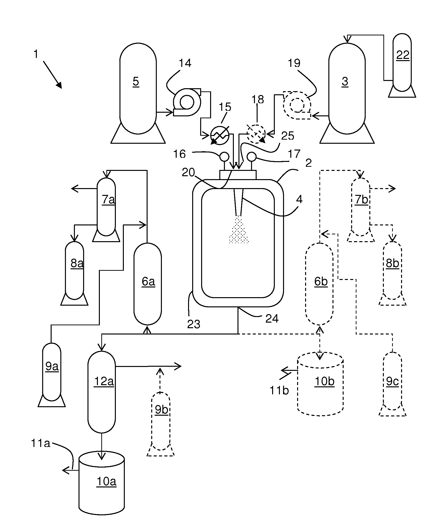
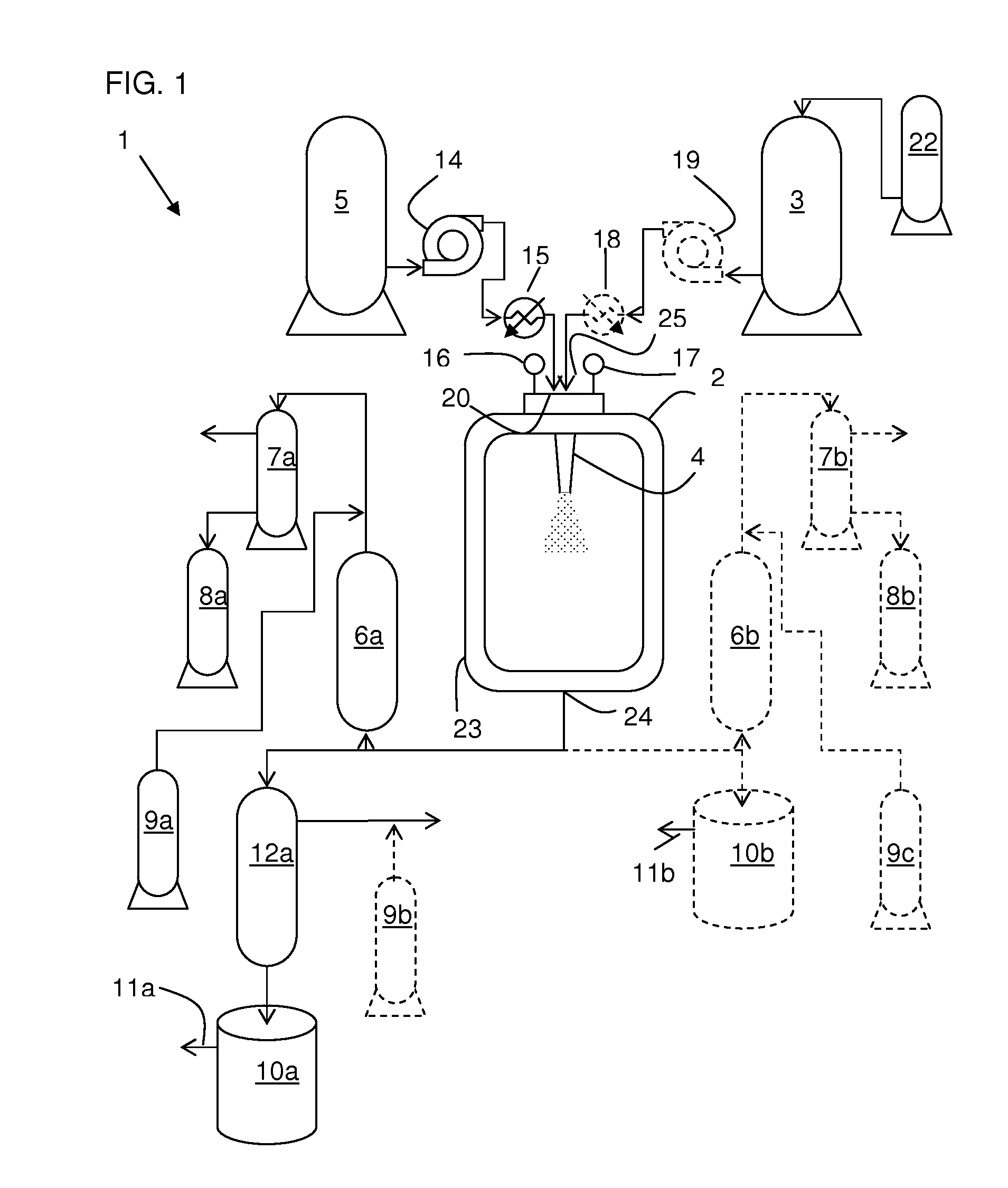
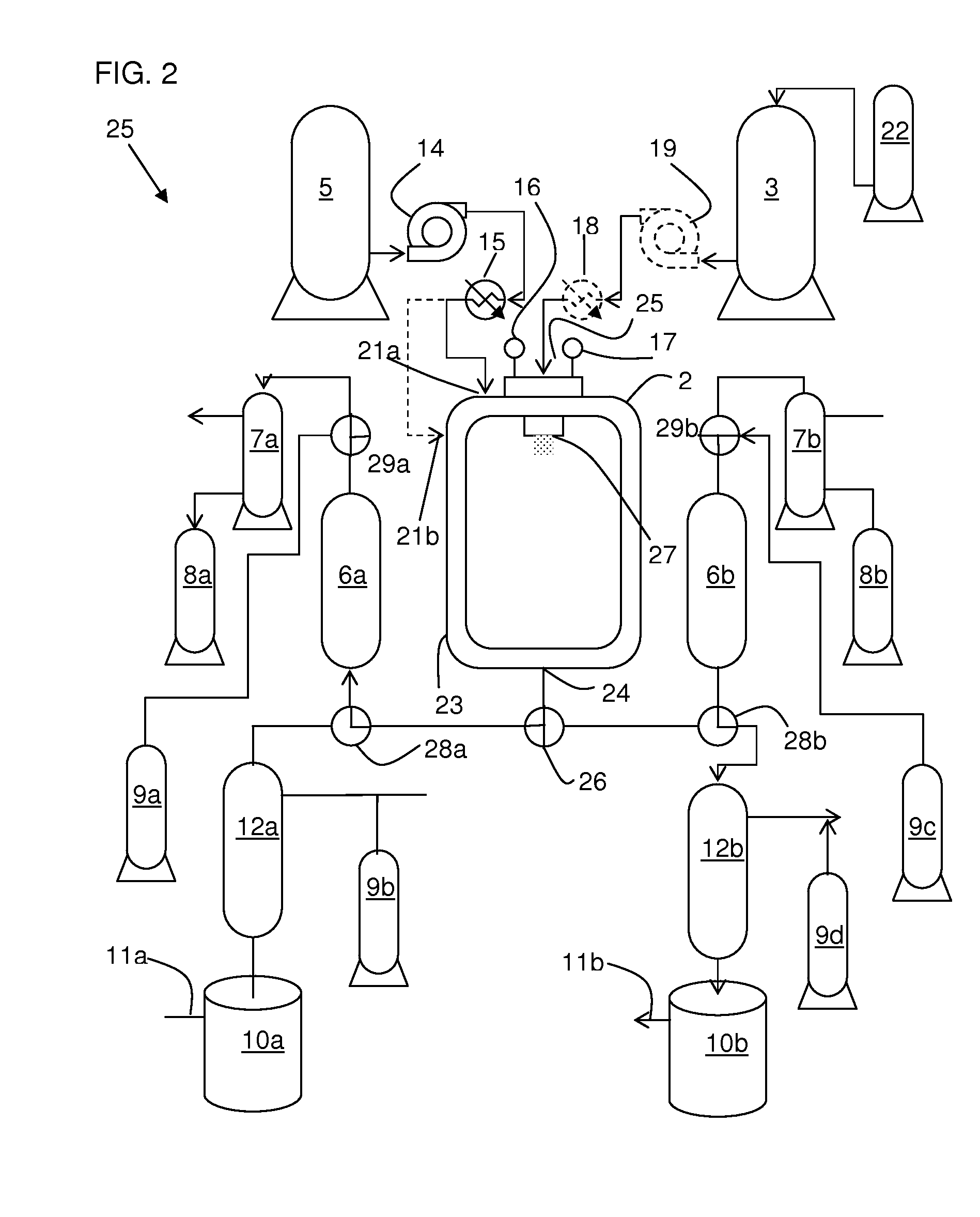
The present invention provides an equipment assembly for the preparation, harvesting, and collection of particles. The assembly includes a high pressure filter system and a low pressure collection filter system. The high pressure system includes a housing with a conical portion and a porous element extending into the housing. The system is designed to collect particles by precipitation and can also remove unwanted components from the particles. The low pressure system includes a housing with an inlet and a gas outlet port and a porous element extending into the housing. The system is designed to collect particles by a low pressure gaseous particle suspension and can also remove solvent from the particles. The invention provides a solution for collecting particles and even washing them with solvent.

Problems solved by technology

A key drawback of such a process, however, is the entrapment of solvent and / or anti-solvent within and / or on the surface of the particles.
Removal of solvent from the particles typically involves washing of the particles with additional amounts of anti-solvent, which unfortunately results in saturation of the particles with anti-solvent, unless the anti-solvent is very volatile.
Solvents, however, are less volatile than the SCF and thus are more difficult to remove.
Due to the extreme volatility of supercritical carbon dioxide, it is a challenge to effectively harvest particles from it unless the particles are first physically separated from it.
When microparticles or nanoparticles are being processed, however, it is more difficult to separate the particles from the SCF due to fouling of filters, and it is difficult to unfoul filters when a process is running.
These challenges make continuous processing and harvesting of particles extremely difficult to achieve.
Many of these systems cannot be operated continually since they require halting of operations and opening of components in the process stream in order to remove particles.
This is particularly difficult to achieve when particle formation is conducted continuously.

Method used


Image

  • Equipment Assembly for and Method of Processing Particles
  • Equipment Assembly for and Method of Processing Particles
  • Equipment Assembly for and Method of Processing Particles

Examples


example 1

[0107]The following process can be used to make particles comprising acetaminophen. The following ingredients in the amounts indicated are used.

INGREDIENTAMOUNT (% WT.)Acetone96.5acetaminophen3.5

[0108]An equipment assembly as depicted in FIG. 5 is employed. A process fluid is prepared by dissolving acetaminophen in ethanol in amounts according to the table above. Dissolution can be done while heating and / or mixing. The anti-solvent is supercritical carbon dioxide (scCO2).

[0109]The precipitation chamber is charged with scCO2 and its temperature and pressure are equilibrated. The pressure is about 1,200 psi and the temperature is about 38° C. Flow of scCO2 through the precipitation chamber is initiated. Clean solvent is conducted through an atomizer, comprising a vibrating porous mesh and a capillary nozzle upstream of the mesh, by way of an inlet in the precipitation chamber, whereby it is atomized directly into the scCO2. The flow rate (about 730 ml / min) of scCO2 into the chamber ex...

example 2

[0112]The following process can be used to make particles comprising paclitaxel and PLGA (poly-(lactic acid)-co-(glycolic acid) polymer). The following ingredients in the amounts indicated are used.

INGREDIENTAMOUNT (% WT.)Acetone96Paclitaxel2.5PLGA1.5

[0113]The process of Example 1 is followed with the following exceptions.

[0114]The process fluid is prepared by dissolving paclitaxel and PLGA in acetone in amounts according to the table above.

example 3

[0115]The following process can be used to make particles comprising meloxicam. The following ingredients in the amounts indicated are used.

INGREDIENTAMOUNT (% WT.)Acetone:DMF 20:8096.8meloxicam3.2

[0116]An equipment assembly as depicted in FIG. 5 is employed. A process fluid is prepared by dissolving meloxicam in acetone / dimethylformamide (20:80) in amounts according to the table above. Dissolution can be done while heating and / or mixing. The anti-solvent is supercritical carbon dioxide (scCO2).

[0117]The precipitation chamber is charged with scCO2 and its temperature and pressure are equilibrated. The pressure is about 1,200 psi and the temperature is about 38° C. Flow of scCO2 through the precipitation chamber is initiated. Clean solvent is conducted through an atomizer, comprising a vibrating porous mesh and a capillary nozzle upstream of the mesh, by way of an inlet in the precipitation chamber, whereby it is atomized directly into the scCO2. The flow rate (about 730 ml / min) of s...


PUM

PropertyMeasurementUnit
diameteraaaaaaaaaa
outer diameteraaaaaaaaaa
pressureaaaaaaaaaa

Abstract

An equipment assembly for preparing, harvesting and collecting particles is disclosed. The assembly comprises a tandem filter system with one or more high pressure filters, one or more low pressure filters and one or more collection vessel. Particles can be prepared, harvested and collected continuously, semi-continuously or in a batch-type operation. A tandem filter system and its method of use are also disclosed. Particles made with the assembly and according the instant methods are also disclosed. The assembly provides improved particle harvesting and collection over other systems and permits continuous particle formation, in particular by dispersion of a solute-containing process fluid within a supercritical anti-solvent.

Description

CROSS-REFERENCE TO EARLIER-FILED APPLICATION[0001]The present application is a continuation of and claims the benefit of U.S. Ser. No. 13 / 911,700, filed Jun. 6, 2013, which claims the benefit of U.S. 61 / 783,682, filed Mar. 14, 2013, the entire disclosures of which is hereby incorporated by reference.FIELD OF THE INVENTION[0002]The present invention concerns an apparatus for processing particles. More particularly, the invention concerns a tandem filtration system for processing particles suspended in supercritical fluid. Methods for processing the particles to remove contaminants or to classify them are also provided.BACKGROUND OF THE INVENTION[0003]Particles can be prepared by adding a solubilized compound, i.e. a compound dissolved in one or more solvents, to an anti-solvent. Such a process can be used to prepare particles in many different size distributions. A key drawback of such a process, however, is the entrapment of solvent and / or anti-solvent within and / or on the surface o...

Claims


Application Information

Patent Timeline
Patent Type & Authority Applications(United States)
IPC IPC(8): B01J8/00
CPCB01J8/006B01J4/002B01D9/0013B01D9/0054B01J3/008Y02P20/54A61J3/02B01D11/0411B01D46/71
Inventor JOHNSON, GREG S.SUBRAMANIAM, BALANIU, FENGHUI
Owner CRITITECH INC
Learn More