Stress monitoring device of elasto-magneto-electric (EME) effect type

a technology of elastomagnetoelectric and stress monitoring device, which is applied in the direction of tension measurement, instrumentation, structural/machine measurement, etc., can solve the problems of inconvenient installation, inability to use pressure sensors in dynamic stress monitoring of in-service structures, and inability to achieve measurement results. , to achieve the effect of reducing weight and size of the device, reducing interference, and prolonging the service li

Active Publication Date: 2014-10-09
ZHEJIANG UNIV
View PDF2 Cites 21 Cited by
  • Summary
  • Abstract
  • Description
  • Claims
  • Application Information

AI Technical Summary

Benefits of technology

[0019]In a class of the embodiment, the magnetic field generating unit, the ME sensing unit, the support skeleton unit, the signal controlling and conditioning instrument, or parts thereof, or the entire monitoring device is installed with a protection cover. The protection cover not only shields the external magnetic field to reduce interference with the internal magnetic field and signals, but also protects the entire monitoring device from external damage to prolong the service life of the device.
[0020]The stress monitoring device of the present invention uses ME sensing unit to replace the signal-integration-required secondary coil as the signal detecting element. The ME sensing unit is made of ME laminated composite, and correspondingly the ME sensing unit is able to monitor real-time changes in magnetic field intensity (the response time for the monitoring is in order of milliseconds). The size of the ME sensing unit is small, and correspondingly the weight and size of the device is effectively reduced. The ME

Problems solved by technology

However, due to the characteristics of the pressure gauge, including the instability in the indicator reading, the necessity to convert the reading to the load value, and large influence by human factor, the pressure sensor is unavailable in the dynamic stress monitoring for the in-service structures.
Therefore, when using the above mentioned three methods, the installation is inconvenient and the measurement results are susceptible to influences of external factors.
For in-service structures, the resistance strain sensor, vibrating wire strain sensor, or optical fiber grating strain sensor can only measure the changes of the strain/stress (namely, the increment) relative to initial strain/stress after installation or zero setting, but cannot measure the actual absolute value of the strain/stress.
However, there are disadvantages for the method of monitoring cable force by measuring vibration frequency: (1) the relationship between the cable force and the vibration frequency is affected by flexural rigidity, slope, sag, boundary conditions, and the vibration reducing and damping device of the cable, which causes errors in the conversion of the cable force; (2) the converted cable force is static value or averaged value, correspondingly, it is impossible to obtain the variations of the cable force in periodic vibration; and (3) the method is not suitable for

Method used


Image

  • Stress monitoring device of elasto-magneto-electric (EME) effect type
  • Stress monitoring device of elasto-magneto-electric (EME) effect type
  • Stress monitoring device of elasto-magneto-electric (EME) effect type

Examples


Embodiment Construction

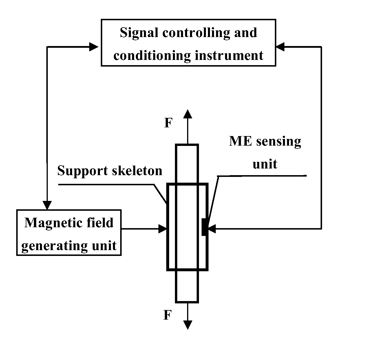
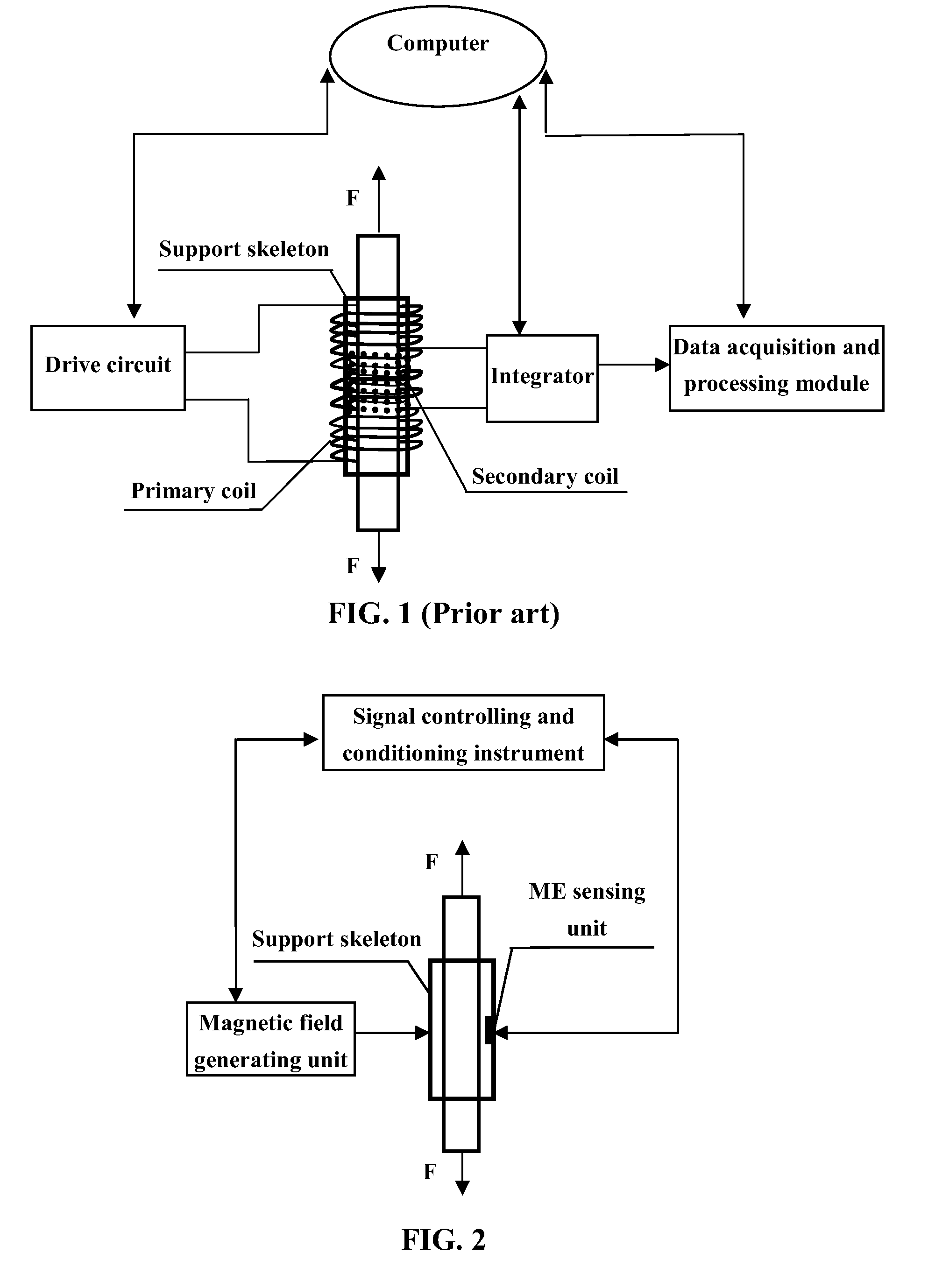
[0070]FIG. 2 illustrates an exemplary embodiment of a stress monitoring device of EME effect type of the present invention. The stress monitoring device of the present invention comprises a magnetic field generating unit, one or more ME sensing units, one or more support skeletons, and a signal controlling and conditioning instrument. In this invention, the ME sensing units are used to replace the secondary coil of the conventional Magneto-Elastic cable force sensor shown in FIG. 1 to generate sensing signals. The ME sensing units possess the following advantages: 1) being capable of producing a strong output signal in proportional to the external force (i.e., good linearity in the mechanical-magneto-electric coupling); 2) being sensitive to the variances of the external force; and 3) being installed easily and stably.

[0071]In the present invention, under the control of signal controlling and conditioning instrument, the magnetic field generating unit creates a magnetic field in the...


PUM


Abstract

A stress monitoring device of elasto-magneto-electric (EME) effect type, for monitoring stress of a structural component of ferromagnetic materials, includes a magnetic field generating unit, a magneto-electric (ME) sensing unit, a support skeleton, and a signal controlling and conditioning instrument. Under the control of the signal controlling and conditioning instrument, the magnetic field generating unit generates a magnetic field for magnetizing the structural component. The ME sensing unit outputs an electrical signal VME characterizing the magnetic field without a need of external power supply. This electrical signal VME is analyzed and processed by the signal controlling and conditioning instrument to output a magnetic characteristic value Vst corresponding to the changes of the external forces that are exerted on the component. This stress monitoring device realizes on-line, real-time, and nondestructive monitoring, as well as off-line nondestructive monitoring.

Description

CROSS-REFERENCE TO RELATED APPLICATIONS[0001]This application is a continuation-in-part of International Patent Application No. PCT / CN2012 / 085367 with an international filing date of Nov. 27, 2012, designating the United States, now pending, and further claims priority benefits to Chinese Patent Application No. 201110389375.8 filed Nov. 30, 2011. The contents of all of the aforementioned applications, including any intervening amendments thereto, are incorporated herein by reference. Inquiries from the public to applicants or assignees concerning this document or the related applications should be directed to: Matthias Scholl P. C., Attn.: Dr. Matthias Scholl Esq., 14781 Memorial Drive, Suite 1319, Houston, Tex. 77079.BACKGROUND OF THE INVENTION[0002]1. Field of the Invention[0003]The present invention relates to a stress monitoring device of elasto-magneto-electric (EME) effect type, and specifically to a non-destructive stress monitoring device for structural components of ferroma...

Claims


Application Information

Patent Timeline
IPC IPC(8): G01L1/12
CPCG01L1/12G01L1/125G01M5/0025G01L3/102G01L3/104G01L5/10
Inventor DUAN, YUANFENGOR, SIUWINGZHANG, RUFAN, KEQINGZHAO, YANG
Owner ZHEJIANG UNIV
Why Eureka
Try Eureka