
Method of forming densified layer in spray coating, and spray coating covering member

Inactive Publication Date: 2014-10-09
TOCALO CO LTD
View PDF3 Cites 14 Cited by
  • Summary
  • Abstract
  • Description
  • Claims
  • Application Information

AI Technical Summary

Benefits of technology

The present invention allows for two laser beams to be combined and directed towards a targeted area. This creates a layer of dense material that can easily extend deeper into the targeted area, while still maintaining sufficient effectiveness. Additionally, this method prevents the need for expensive and time-consuming treatments, and helps to prevent excessive damage to the coating.

Problems solved by technology

Generally, the process of manufacturing semiconductors, liquid crystal devices and the like has a problem that various members placed in a treating container are corroded because a treatment gas including a fluoride or a chloride is used in the treating container.
Since the presence of particles generated in the treating container badly affects the quality and yield of products, it is absolutely necessary to reduce particles.
However, sufficient effect of corrosion resistance may not be necessarily obtained under such a condition that a severer corrosive gas is present or the like.
In addition, generation of particles having a very small size, which have not been mentioned heretofore, is seen as a problem in the manufacturing process that continues to be downsized.
When the coating composition in the surface layer of the spray coating is remelted and resolidified with the laser beam as described above, cracks may be generated due to solidification / shrinkage of the surface layer.
If cracks are excessively large, however, the corrosion resistance and the particle reducing effect are inversely impaired.

Method used


Image

  • Method of forming densified layer in spray coating, and spray coating covering member
  • Method of forming densified layer in spray coating, and spray coating covering member
  • Method of forming densified layer in spray coating, and spray coating covering member

Examples


example

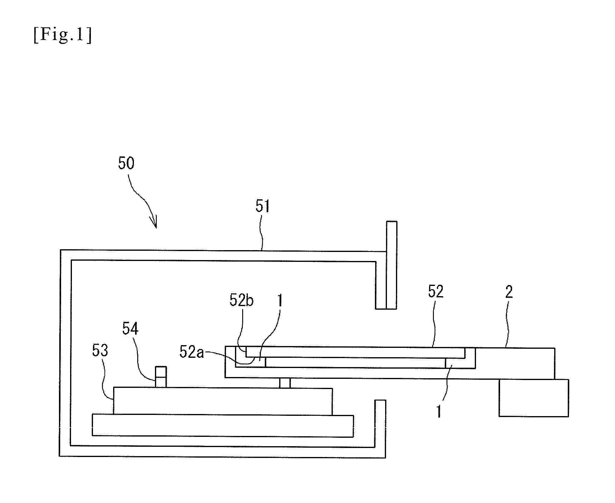
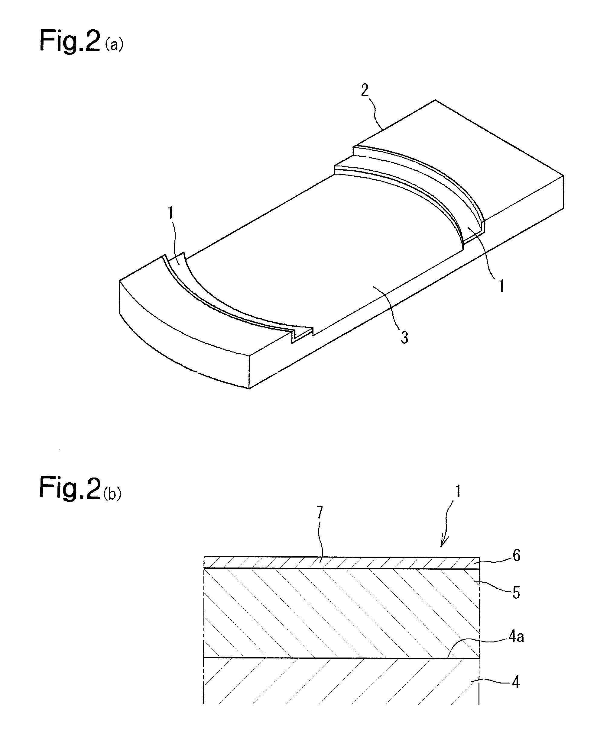
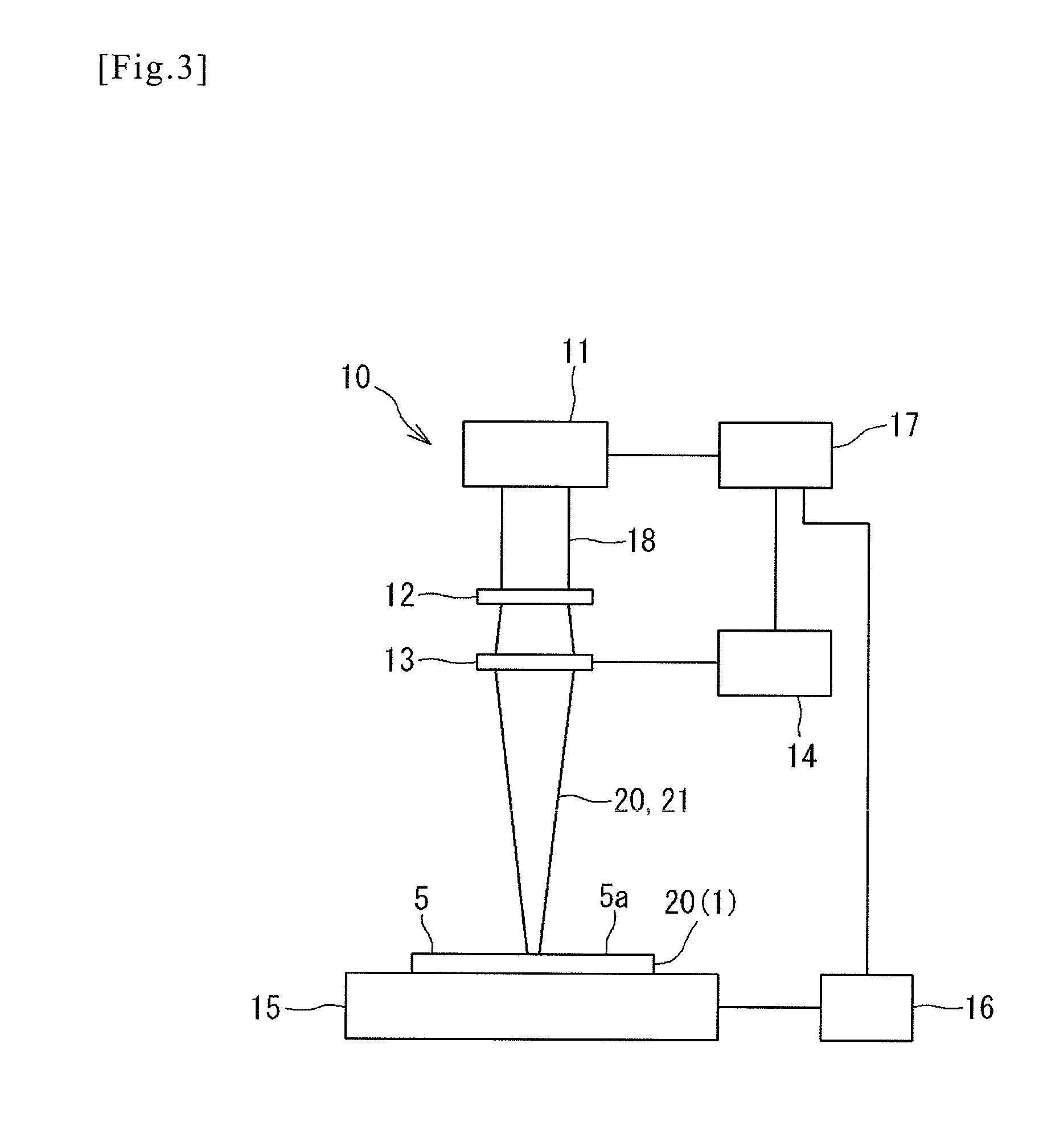
[0083]The present invention will be described in detail by way of an example. Moreover, the present invention is not limited to the following example. As the example, one surface of a flat plate A 6061 of 100×100×5 mm is coated with an Al2O3 spray coating in a thickness of 200 μm with a plasma spraying method and irradiated with a plurality of CO2 laser beams by the method of the second embodiment. The overlapping degree over a spot region in the lateral direction between the adjoining precedent beam spot and follow-up beam spot is 66%. As Comparative Examples 1 and 2, one surface of a flat plate A 6061 of 100×100×5 mm is coated with an Al2O3 spray coating in a thickness of 200 μm with a plasma spraying method and irradiated with a single CO2 laser beam.

[0084]The irradiation conditions in the example and Comparative Examples 1 and 2 are as follows.

[0085](Example) number of beams: 7, laser output: 20 W (2.9 W×7), laser beam area: 0.2 mm2 (0.029 mm2×7), treating speed: 10 mm / s.

[0086](...


PUM

PropertyMeasurementUnit
Compositionaaaaaaaaaa
Energy densityaaaaaaaaaa

Abstract

Forming a densified layer in a spray coating which forms a densified layer providing a sufficient effect while preventing generation of excessively large cracks and does not cause the increase of costs; also provided in a spray coating covering member. When a high-energy beam for remelting and resolidifying a coating composition of a surface layer of an Al2O3 spray coating is scanned over a surface of the Al2O3 spray coating, it is constituted with a precedent laser beam precedently scanned in a scanning direction and a follow-up laser beam subserviently scanned on the same trajectory as that of the precedent laser beam, and the precedent laser beam is irradiated on to the surface of the Al2O3 spray coating while scanning, and the follow-up laser beam is superimposedly irradiated to an irradiation region scanned with the precedent laser beam while scanning to thereby densify the surface layer of the irradiation region.

Description

TECHNICAL FIELD[0001]The present invention relates to a method of forming a densified layer in a spray coating by forming a spray coating on a base member and remelting and resolidifying a surface layer of the spray coating to form a densified layer as well as a spray coating covering member coated with the spray coating.BACKGROUND ART[0002]The spraying method is a surface treating technique wherein a powdery material of a metal, ceramic or the like is supplied into a burning flame or a plasma flame to render into a softened or melted state and sprayed onto a surface of a base member at a high speed to form a spray coating on the surface. As an application of the spraying method is mentioned the formation of a coating on a component member constituting a semiconductor manufacturing device such as CVD apparatus, PVD apparatus, a resist coating apparatus or the like. Generally, the process of manufacturing semiconductors, liquid crystal devices and the like has a problem that various ...

Claims


Application Information

Patent Timeline
IPC IPC(8): B05D3/06B23K26/04B23K26/34C23C4/11C23C4/18
CPCB05D3/06B23K26/0608B23K26/0853B23K26/34C23C4/10C23C4/18
Inventor INABA, MITSUHARUYOKOTA, HIROKI
Owner TOCALO CO LTD
Learn More