Mist/Dust Collector

a technology of dust collectors and dust collectors, applied in the field of collectors, can solve the problems of increasing manufacturing costs, and achieve the effects of reducing manufacturing costs, improving collection efficiency, and efficient collection of dus

Active Publication Date: 2014-10-16
ANLET CO LTD
View PDF2 Cites 31 Cited by
  • Summary
  • Abstract
  • Description
  • Claims
  • Application Information

AI Technical Summary

Benefits of technology

[0013]The above-described mist/dust collector is mainly constructed to be suitable for collection of chips or shavings generated during machining of machine parts, components or the like by a machine tool. Dust can efficiently be collected by a synergistic action of knocking off by a centrifugal force of the disc rotary brush, shaking-off by a centrifugal force of the shaking-off member and filtering by the demister member. In addition, the mist/dust collector employs the structure of rotating the impeller, the rotary brush and the shaking-off member by a synergistic action of collision of a powerful air flow caused by actuation of the suc

Problems solved by technology

Each of the above-mentioned collectors necessitates the motor driving the rotary brush and a cont

Method used


Image

  • Mist/Dust Collector
  • Mist/Dust Collector
  • Mist/Dust Collector

Examples


first embodiment

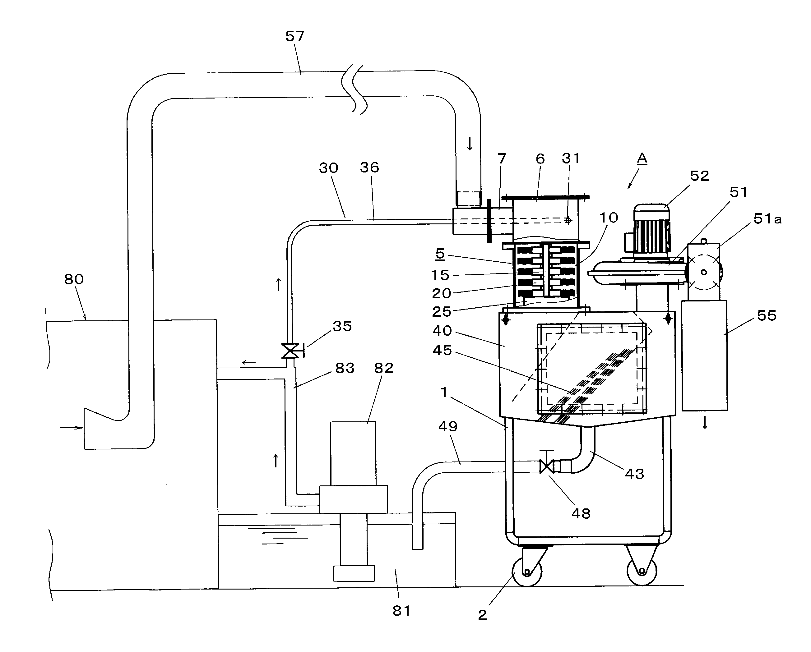
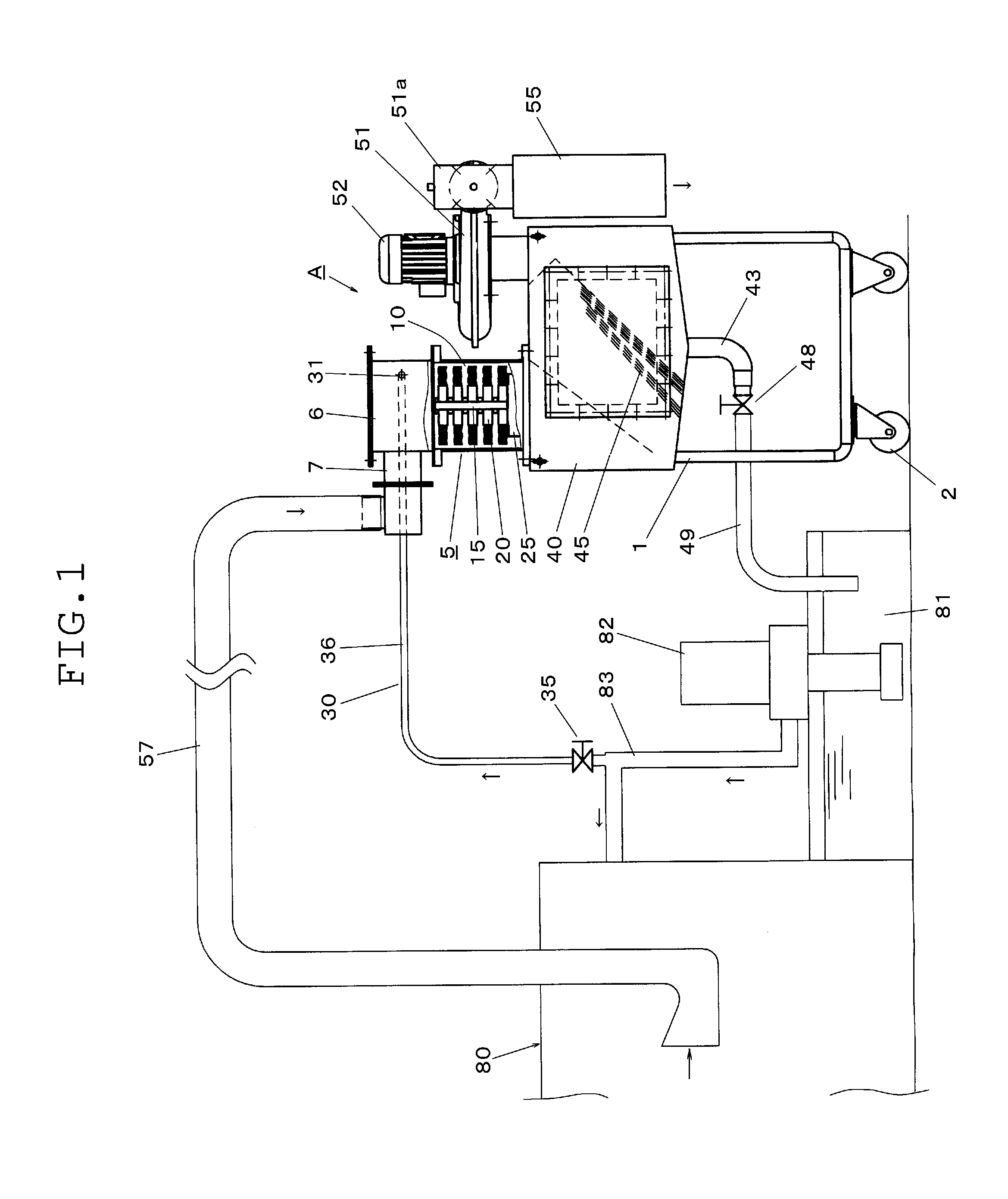
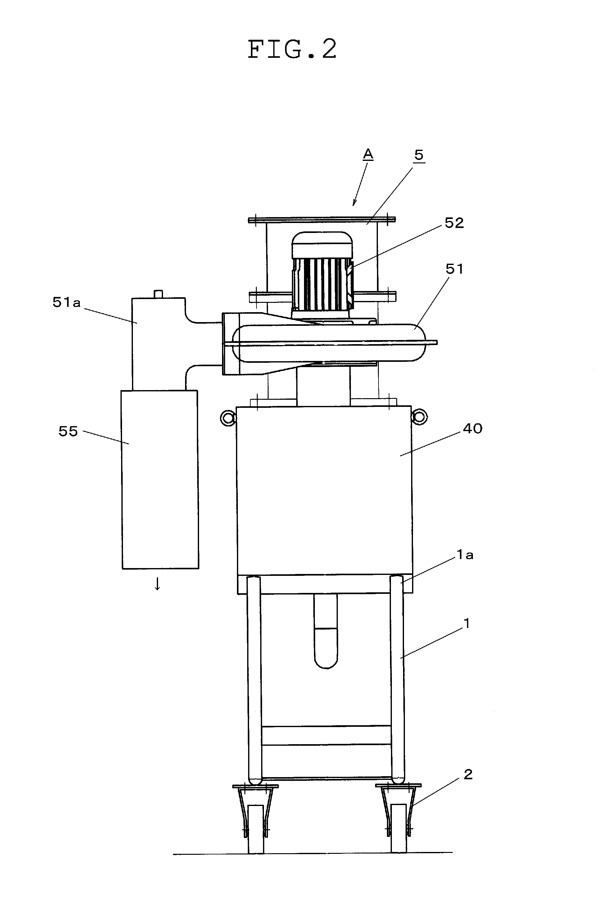
[0036]The following will describe the application of the mist / duct collector A of the first embodiment to a grinding machine.

[0037](1) A grinding machine 80 is constructed to spray coolant fluid toward works and grind stone (not shown) from a nozzle (not shown) during grinding of iron or non-iron works. Consequently, part of the coolant fluid is converted into mist, which is diffused in a closed space of the grinding machine 80.

[0038](2) Upon operation of the collector A, the interior of the tank 5 is maintained in the negative pressure state by operation of the turbofan 51. Accordingly, the mist produced during the grinding is drawn through the suction into the introduction chamber 6 of the tank body 5 together with air therearound.

[0039](3) The impeller 17 is rotated by collision of the air flowing through the inlet 7 into the tank body 5 and the coolant fluid sprayed from the nozzle 31 at a predetermined pressure and simultaneously, the disc rotary brush 20 is rotated at about 50...

second embodiment

[0045]FIG. 7 illustrates a mist / duct collector B in accordance with a The mist / dust collector B is constructed to be suitable for collection of dust, such as chips, produced when machine parts 91 and the like are machined by a machining center and in particular, iron fine dust.

[0046]The mist / dust collector B differs from the mist / dust collector A in the provision of a magnet separator and has the construction based on that of the mist / dust collector A in the other respect. Accordingly, identical or similar parts in the second embodiment are labeled by the same reference symbols as those in the first embodiment and the description of these identical parts will be eliminated.

[0047]A water tank 61 is installed below the recovery tank 40 to store tap water or well water. The collector B includes a spraying unit 60 which is constructed to supply the tap water or well water stored in the water tank 61 through a pipe 63 into the nozzle 31 by a circulation pump 62. A joint 65 is provided f...


PUM

PropertyMeasurementUnit
Pressureaaaaaaaaaa

Abstract

A mist/dust collector includes a tank body, a recovery tank having a demister member, a spraying unit spraying water or coolant fluid from a nozzle, an impeller mounted on a main shaft located in the tank body, so as to be rotatable by air flow, a disc rotary brush and a shaking-off member mounted on the shaft. A suction unit is actuated to draw air containing mist and dust into the tank body interior maintained in a negative pressure state. The impeller is rotated by collision of water or coolant fluid at a predetermined pressure, and the rotary brush and the shaking-off member are rotated simultaneously with the impeller, so that mist and dust are separated from air by a centrifugal action of the rotary brush and the shaking-off member. Mist and dust remaining in the air flowing into the recovery tank are collected by the demister member.

Description

CROSS-REFERENCE TO RELATED APPLICATIONS[0001]This application is based upon and claims the benefit of priority from the prior Japanese Patent Application No. 2013-83517 filed on Apr. 12, 2013, the entire contents of which are incorporated herein by reference.BACKGROUND[0002]1. Technical Field[0003]The present disclosure relates to a collector which collects mist arising from machining of machine parts and components by a machine tool and fine dust such as chips, shavings and grinding sludge to prevent the mist and fine dust from scattering around.[0004]2. Related Art[0005]Various types of structures have conventionally been known as mist / dust collectors. These types include a filter type, a demister type, a cyclone type, a collision plate type and an electrical precipitation type. For example, Japanese Patent No. 4118851 granted to the applicant of the present patent application discloses a mist / dust collector including a separation tank eliminating mist and dust from air, an electr...

Claims


Application Information

Patent Timeline
IPC IPC(8): B01D50/00B03C1/30B01D45/08B01D45/14
CPCB01D50/00B01D45/08B03C1/30B01D45/14B03C1/025B03C2201/20Y02P70/10
Inventor YOKOI, YASUNAITOKATO, TOSHIAKIKUME, KOUITIOKANO, HIDEYUKI
Owner ANLET CO LTD
Why Eureka
Try Eureka