Launch vehicle and system and method for economically efficient launch thereof

a technology of a payload and a launch vehicle, which is applied in the field of systems, methods and apparatuses for the launch of a payload, can solve the problems of increasing aerodynamic drag, unable to launch, and limited launch conditions for humans, etc., and achieves low drag, low pressure moment, and high permeability material

Active Publication Date: 2014-10-16
8 RIVERS CAPTTAL LLC
View PDF24 Cites 25 Cited by
  • Summary
  • Abstract
  • Description
  • Claims
  • Application Information

AI Technical Summary

Benefits of technology

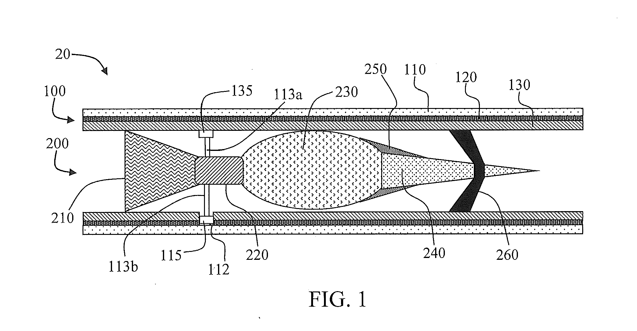
[0043]The flyout payload can have a heat shield with a porous nosetip filled with a material (e.g., solid hydrogen or lithium or ice) that absorbs heat by melting and / or vaporization and / or disassociation to maintain the nosetip integrity, shape, sharpness, low drag, and low pressure moment during exit from the atmosphere. The flyout payload nosetip may include an extruding rod, which can be forced outward as the rod ablates.
[0044]The electrical energy for the launch system can be supplied by a battery bank. In various embodiments, the batteries can be lead acid batteries. Automotive batteries may be used in some embodiments. An inductor can be interposed between the battery bank and the launcher such that the battery bank charges the inductor and then the inductor is switched over to and discharges into the launcher tube. The discharge into the launcher can be initiated by explosively actuated switches. The discharge switching can be accomplished with conventional switches with capacitor mediated arcing control. The inductor can have a core composed of a high permeability material. The core can be designed for high discharge rates and low eddy current losses. The inductor can be actively cooled and / or the core can be actively cooled. In some embodiments, the conductors can be actively cooled.

Problems solved by technology

This can function to insulate the tube walls and can be configured such that there is insufficient time for the gas to expand from the wall into the majority of the tube diameter and thus increase aerodynamic drag.
Further, launch conditions for humans, etc. can be limited such as to about 2 G's to no more than 60 G's acceleration.
Further, the launch can be aborted by destroying the launch package immediately or shortly after its exit from the launch tube.
Key problem is that the drive voltages required are:
It is believed that no previous work has heretofore achieved voltages over about 50,000 volts in a coil launcher, and this among other factors has limited the velocities that can be attained.

Method used


Image

  • Launch vehicle and system and method for economically efficient launch thereof
  • Launch vehicle and system and method for economically efficient launch thereof
  • Launch vehicle and system and method for economically efficient launch thereof

Examples


example

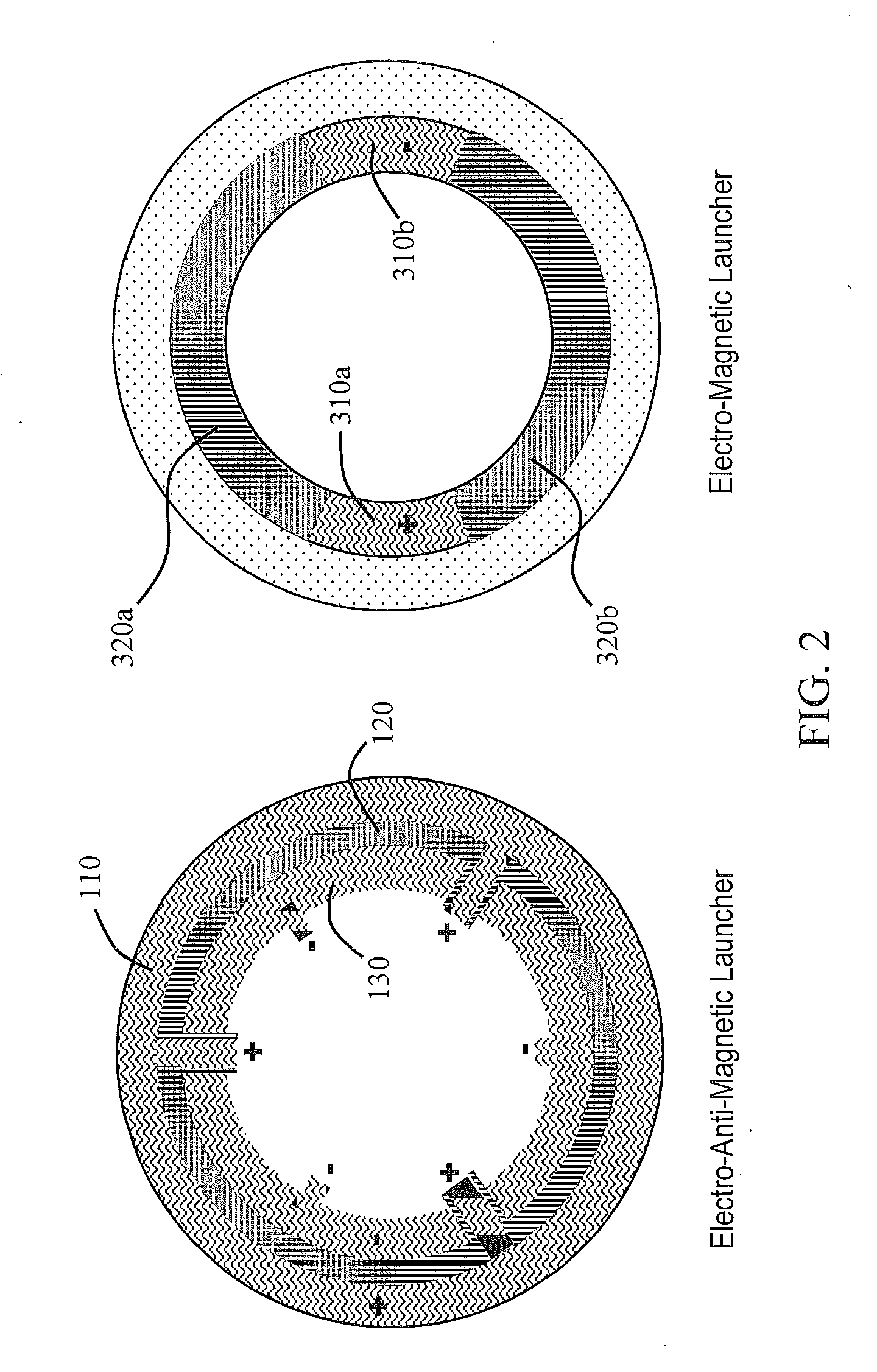
[0217]Mathematical modeling of launch systems was carried out to exemplify the advantages of the presently disclosed EAM launcher, particularly in relation to typical, prior art EM launchers. Prior art EM launcher modeling was based upon the following equation:

F=MA=0.5×L′×I2

wherein F is force in Newtons, M is mass in kg, A is acceleration in meters per second squared, L′ is the increase in inductance per meter of travel in the launch tube in microhenries per meter, and I is current in amps.

Modeling of a Typical Known Art Railgun (for a 1 Ton Payload)

[0218]Modeling for a prior art railgun was carried out as follows:

[0219]L′=5×10⁻⁷ H / m;

[0220]I=20×106 A;

[0221]M=1,000 kg;

[0222]F=0.5×(5×10−7)×(20×106)2=0.5×(5×10−7)×(400×1012)=1×10⁸N

[0223]A=F / M=1×10⁵ m / sec2=10,000 G's.

[0224]Typical efficiency historically demonstrated by EM railguns for only a few grams at 6000 m / sec has been about 0.1% to 1%.

[0225]Typical efficiency demonstrated by EM railguns for a few hundred grams at 3000 m / sec has b...


PUM


Abstract

The present disclosure relates to a launch system, a launch vehicle for use with the launch system, and methods of launching a payload utilizing the launch vehicle and/or the launch system. The disclosure can provide for delivery of the payload at a terrestrial location, an Earth orbital location, or an extraorbital location. The launch vehicle can comprise a payload, a propellant tank, an electrical heater wherein propellant, such as a light gas (e.g., hydrogen) is electrically heated to significantly high temperatures, and an exhaust nozzle from which the heated propellant expands to provide an exhaust velocity of, for example, 7-16 km/sec. The launch vehicle can be utilized with the launch system, which can further comprise a launch tube formed of at least one tube, which can be electrically conductive and which can be combined with at least one insulator tube. An electrical energy source, such as a battery bank and associated inductor, can be provided.

Description

CROSS-REFERENCE TO RELATED APPLICATIONS[0001]The present application claims priority to U.S. Provisional Patent Application No. 61 / 799,931, filed Mar. 15, 2013, the disclosure of which is incorporated herein by reference in its entirety.FIELD OF THE DISCLOSURE[0002]The present disclosure relates to systems, methods, and apparatuses for launch of a payload. More particularly, the payload may be intended for space launch or delivery to a terrestrial location, and the present disclosure can provide for acceleration of the payload from a launch tube to its desired location.BACKGROUND[0003]Many means are known for accelerating an object. Relatively small projectiles are efficiently accelerated via controlled explosive charges, such as with gunpowder. As the mass of the object being accelerated increases, however, the explosive force required greatly increases. For example, chemical combustion rockets are presently the only means that have been shown to be effective for launching payloads...

Claims


Application Information

Patent Timeline
Patent Type & Authority Applications(United States)
IPC IPC(8): B64G1/40
CPCB64G1/402B64G1/409B64G1/00B64G1/40F41B6/00F42B6/006F41A1/04F42B15/10F42B15/12F41B6/006F02K9/95B64G1/002B64G1/415F41F1/00F42C11/00F41F3/04F41F3/0406F42C11/04
Inventor PALMER, MILES R.BROWN, JR., GLENN WILLIAM
Owner 8 RIVERS CAPTTAL LLC
Why Eureka
Try Eureka