Magnetic field measuring apparatus and method for manufacturing same

a technology of magnetic field and measuring apparatus, which is applied in the direction of magnetic measurement, magnetic field measurement using magneto-optic devices, instruments, etc., can solve the problems of not solving the problem, the pressure cannot be controlled quantitatively in the gas cell, and the magnetic field measurement performance cannot be inspected, so as to facilitate the pressure control and improve the sensitivity

Inactive Publication Date: 2014-10-16
HITACHI LTD
View PDF27 Cites 48 Cited by
  • Summary
  • Abstract
  • Description
  • Claims
  • Application Information

AI Technical Summary

Benefits of technology

[0018]According to the present invention, a magnetic field measuring apparatus or a manufacturing method of the same are provided, which facilitates the pressure control in the gas cell, or capable of inspecting the internal p

Problems solved by technology

However, in the process of generating the buffer gas as a product of the chemical reaction, it is difficult to control the pressure in a quantitative manner in the gas cell, and the magnetic field measuring performance may vary in the manufactured magnetometer.
Therefore, in a gas cell that has been manufactured with a deviation from the pressure of the manufacturing specification, there is also a problem in that the magnetic field measuring performance cannot be inspected until the magnetometer is structured by combining optical components such as a laser and magnetic components such as a coil, or it is necessary to add a troublesome process such as inspection using a measurement system such as a performance evaluation system separately structured for each gas cell.
A method for directly measuring the pressure in the gas cell may be conducting destructive inspection of the gas cell, but this requires a destruction step and an inspection proces

Method used


Image

  • Magnetic field measuring apparatus and method for manufacturing same
  • Magnetic field measuring apparatus and method for manufacturing same
  • Magnetic field measuring apparatus and method for manufacturing same

Examples


first embodiment

Basic Configuration

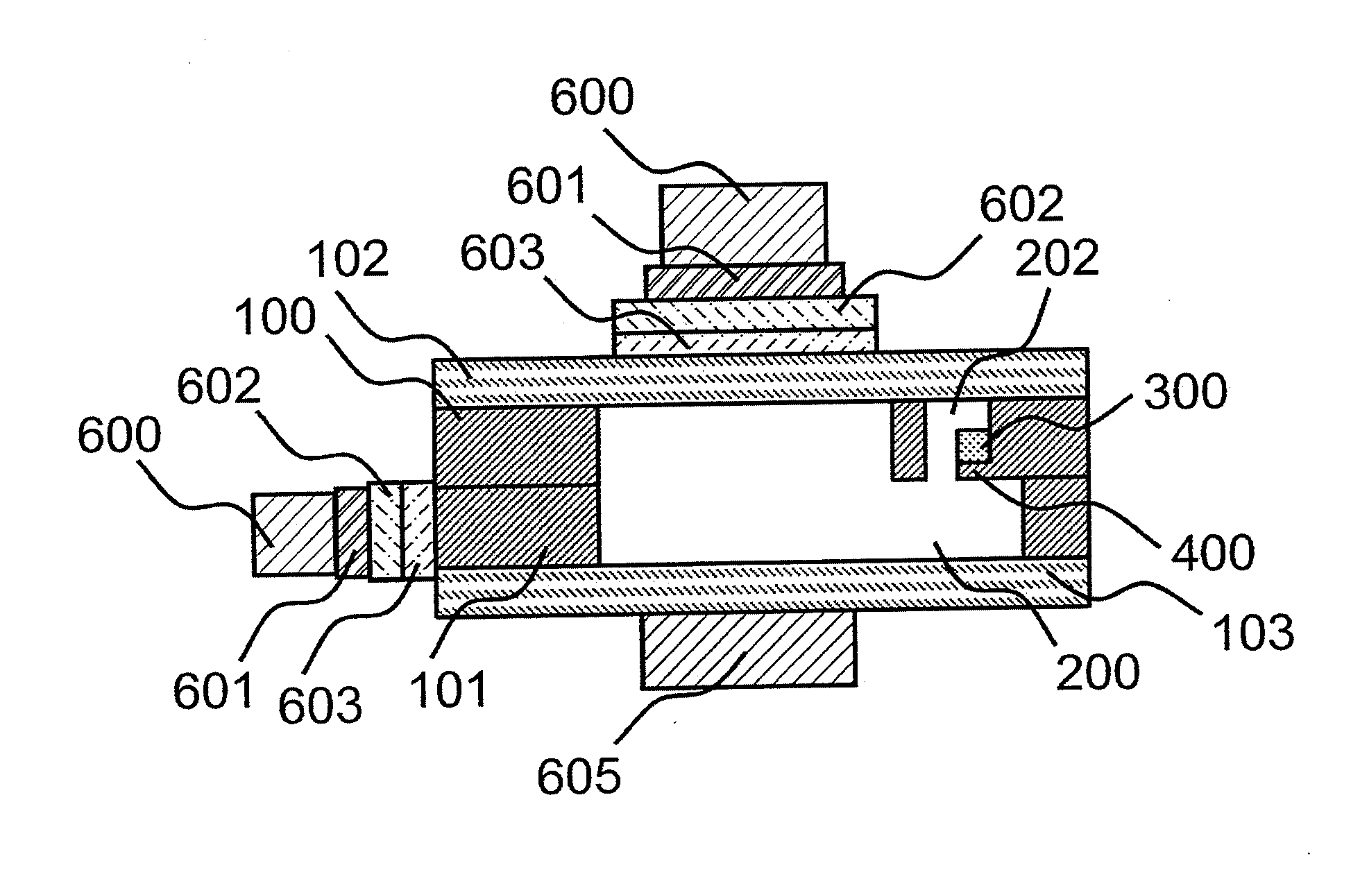
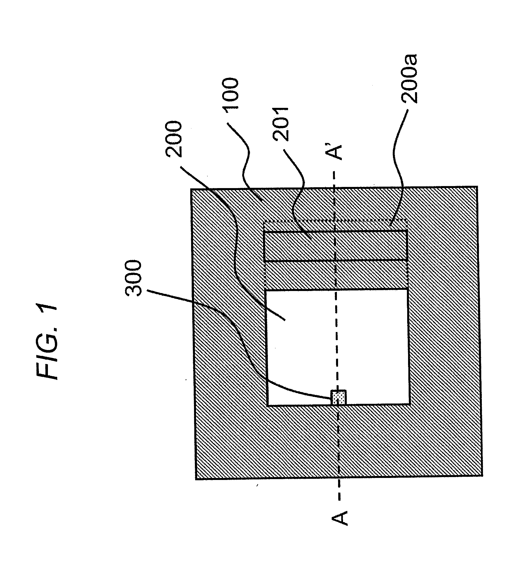
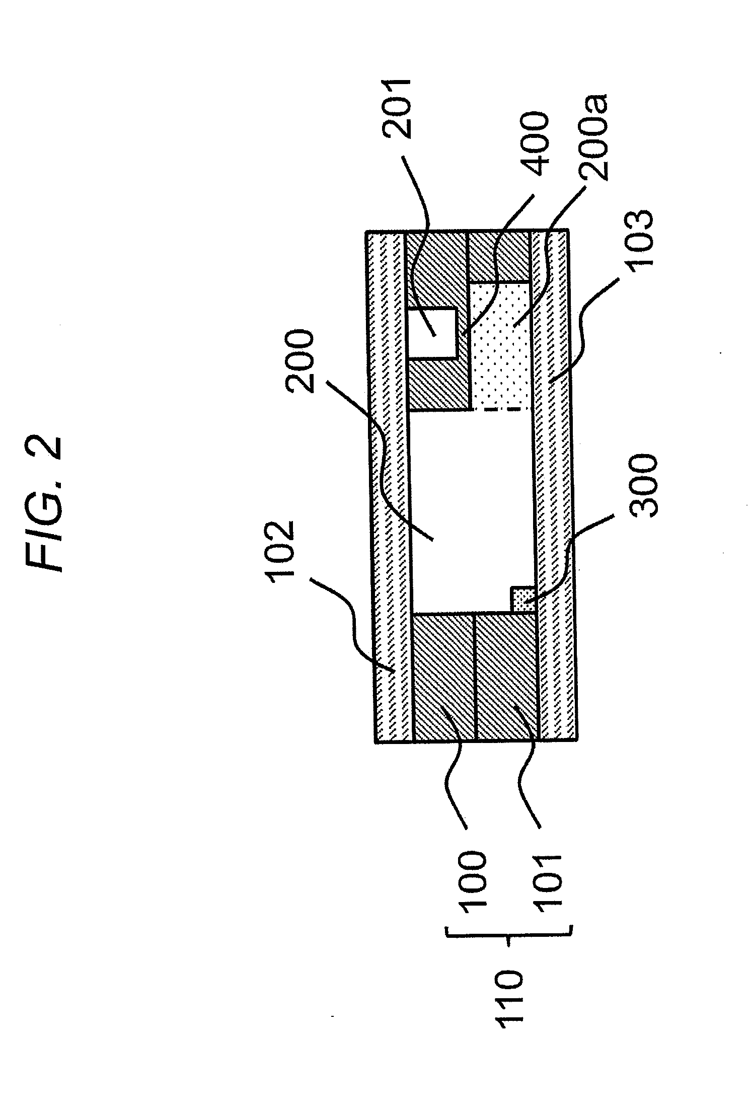
[0044]FIG. 1 is a schematic top view illustrating a magnetic field measuring apparatus (gas cell) according to the first embodiment of the present invention. FIG. 2 is a schematic cross sectional view taken along A-A′ thereof. In FIGS. 1 and 2, a portion of a hollow section 200 is denoted as 200a for the sake of easy understanding. In FIG. 1, a sealing member 102 is omitted for the sake of easy understanding (it is also omitted in the schematic top views subsequent thereto). The hollow section 200a particularly indicates a lower area of non-processed portion of a substrate 100 and an area below the hollow section 201.

[0045]The gas cell of FIG. 2 has such a structure that a process layer 110 is sealed by sealing members 102 and 103. The process layer 110 is an area where the hollow portions 200 and 201 are provided. In the structure of FIG. 2, in particular, it is made of a two-layer structure including the process members 100 and 101.

[0046]In addition, the gas cel...

second embodiment

[0110]FIG. 15 is a schematic top view illustrating a gas cell according to the second embodiment. FIG. 16 is a schematic cross sectional view taken along A-A′ cross section. In FIGS. 15 and 16, a portion of a hollow section 200 is denoted as 200a for the sake of easy understanding. The hollow section 200a particularly indicates a lower area of non-processed portion of the process member 100 and an area below the hollow section 201.

[0111]The gas cell of FIG. 15 has such a structure that a process layer 110 is sealed by sealing members 102 and 103. The process layer 110 is an area where the hollow sections 200 and 202 are provided. In the structure of FIG. 15, in particular, it is made of a two-layer structure including the process members 100 and 101.

[0112]In addition, the gas cell of FIG. 15 includes a sealing member 103, a process member 101, a process member 100, and a sealing substrate 102 which are arranged from the bottom, and has a four-layer configuration including a sealing ...

third embodiment

[0130]FIG. 21 is a schematic top view illustrating a gas cell according to the third embodiment. FIG. 22 is a schematic cross sectional view along A-A′ cross section.

[0131]In FIGS. 21 and 22, a portion of a hollow section 200 is denoted as 200a for the sake of easy understanding. The hollow section 200a particularly indicates a lower area of non-processed portion of the process member 100 and an area below the hollow section 201 and the hollow section 202.

[0132]The gas cell of FIG. 21 has a structure in which the process layer 110 is sealed by the sealing members 102 and 103. The process layer 110 is an area where the hollow sections 200, 201, and 202 are provided. In the structure of FIG. 21, in particular, the process layer 110 has a two-layer structure including the process members 100 and 101.

[0133]In addition, the gas cell of FIG. 21 includes a sealing member 103, a process member 101, a process member 100, and a sealing member 102 which are arranged from the bottom, and has a ...


PUM

PropertyMeasurementUnit
Pressureaaaaaaaaaa
Magnetic fieldaaaaaaaaaa
Wavelengthaaaaaaaaaa

Abstract

In order to provide a magnetic field measuring apparatus facilitating the pressure control in a gas cell, or capable of inspecting the internal pressure of the gas cell without using any special process, the magnetic field measuring apparatus is configured such that a process layer of the magnetic field measuring apparatus has such a structure that includes a first hollow portion and a second hollow portion provided opposed to first hollow portion with a first isolation wall interposed therebetween. Alternatively, a method for manufacturing the magnetic field measuring apparatus includes breaking the first isolation wall after generating alkali metal (FIG. 17 and FIG. 20).

Description

BACKGROUND OF THE INVENTION[0001]1. Field of the Invention[0002]The present invention relates to a structure of a magnetic field measuring apparatus, and more particularly relates to a structure of a gas cell of an optically pumped magnetometer, and a method for manufacturing the apparatus.[0003]2. Description of the Related Art[0004]A high-sensitivity optically pumped magnetometer highly integrated into a small size has been developed, and there is W. Clark Griffith, Svenja Knappe, and John Kitching, “Femtotesla atomic magnetometry in a microfabricated vapor cell”, Optics Express 18, 27167-27172 (2010) as background art in this technical field.[0005]A gas cell of an optically pumped magnetometer described in W. Clark Griffith, Svenja Knappe, and John Kitching, “Femtotesla atomic magnetometry in a microfabricated vapor cell”, Optics Express 18, 27167-27172 (2010) is configured such that both surfaces of a silicon substrate in which a penetrating hole (cavity) is formed are bonded wi...

Claims


Application Information

Patent Timeline
IPC IPC(8): G01R33/032G01R3/00
CPCG01R3/00G01R33/0322G01R33/26Y10T29/49002
Inventor KAMADA, YUDAIOSABE, TAROSUZUKI, SEIICHIKANDORI, AKIHIKOKAWABATA, RYUZO
Owner HITACHI LTD
Why Eureka
Try Eureka