Pipe Centralizer Having Low-Friction Coating

a technology of low friction and centralizer, which is applied in the direction of solid-state diffusion coating, sealing/packing, and borehole/well accessories, etc., can solve the problems of adding complexity and expense to the manufacturing process, and the general cost prohibitive of dlc coating for centralizers

Inactive Publication Date: 2014-10-23
ROCK DICKE
View PDF9 Cites 22 Cited by
  • Summary
  • Abstract
  • Description
  • Claims
  • Application Information

AI Technical Summary

Benefits of technology

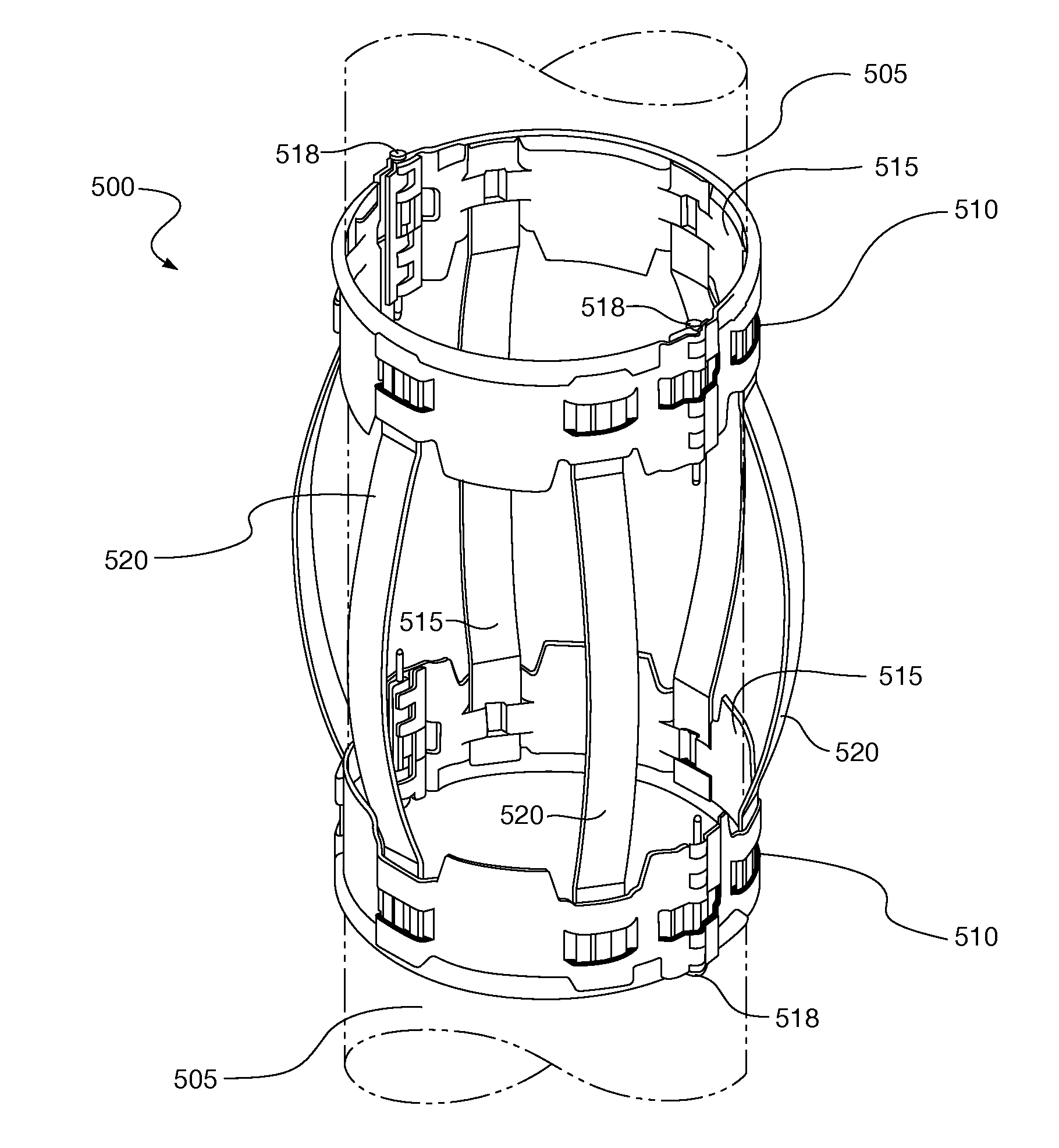
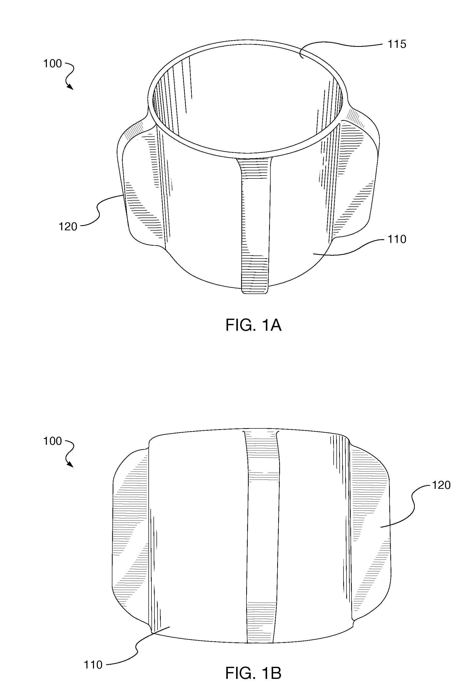
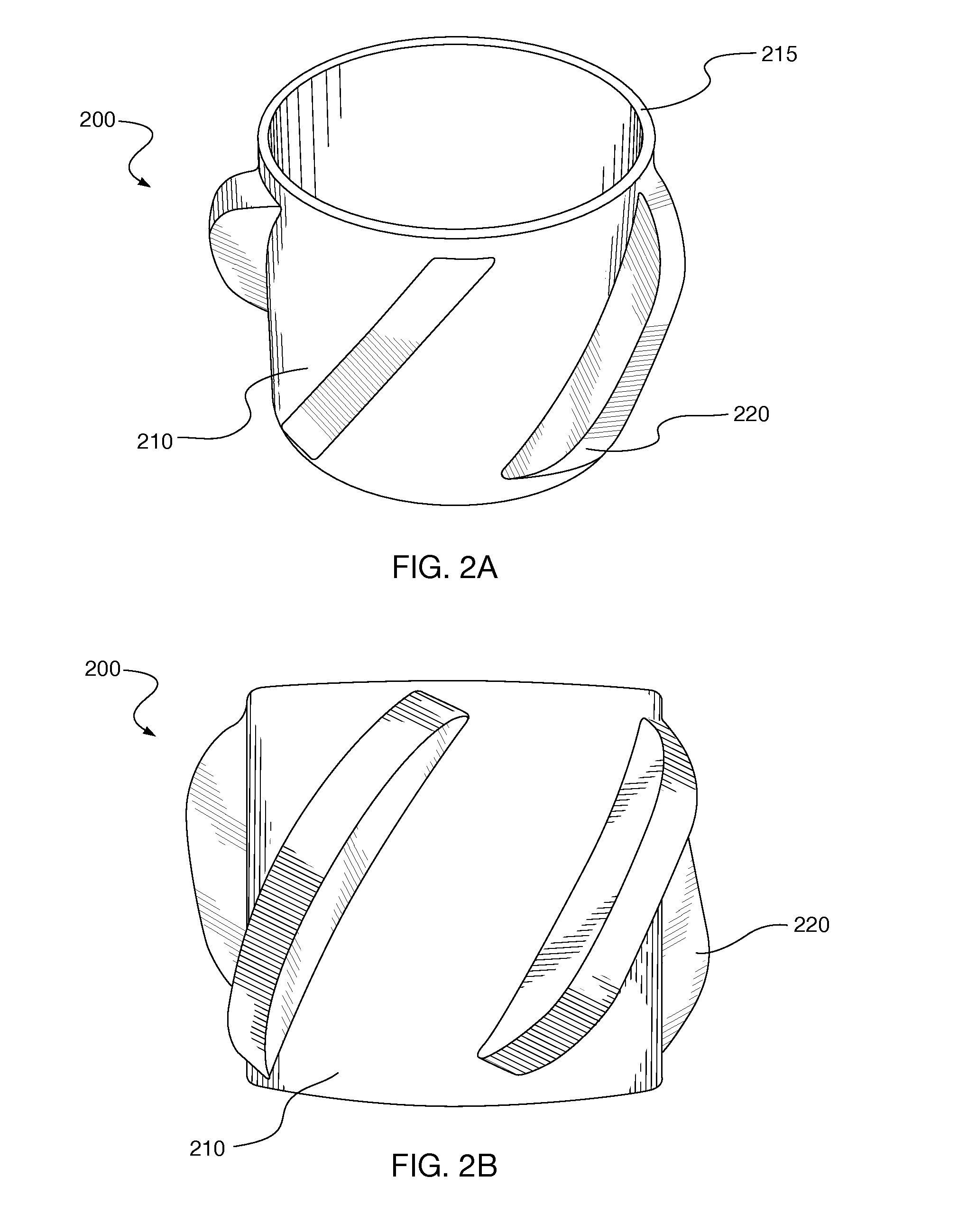
[0022]In one aspect, the low-friction layer resides only on the inner surface of the centralizer. This provides for significantly reduced friction relative to a casing wall, allowing the casing to rotate and translate relative to the centralizer as a casing string is run into a wellbore while still being centralized. In another aspect, the layer also resides along blades on the outer surface of the centralizer. This reduces drag friction and abrasion as the casing with attached centralizers is run into the wellbore. Most preferably, the coating is a polytetrafluoroethylene (PTFE) coating applied on all surfaces.
[0027]The method further optionally includes lowering the pressure in the chamber during deposition. In one aspect, the pressure is lowered to between about one and ten torrs. This assists the deposition process.
[0029]It is preferred that the heating and vapor deposition process be conducted over a period of about one hour. Preferably, a terrific nitrocarburizing process is employed that produces a polytetrafluoroethylene (PTFE) coating on all surfaces. Thereafter, the deposition chamber is allowed to cool. As the centralizer cools within the deposition chamber, the inert nano-particles become trapped or embedded into the metal material. In this way, a low-friction coating is formed.

Problems solved by technology

However, this adds complexity and expense to the manufacturing process and does nothing to reduce friction along surfaces contacting casing joints.
However, DLC coatings are generally cost prohibitive for centralizers.

Method used


Image

  • Pipe Centralizer Having Low-Friction Coating
  • Pipe Centralizer Having Low-Friction Coating
  • Pipe Centralizer Having Low-Friction Coating

Examples


Embodiment Construction

Definitions

[0041]For purposes of the present application, it will be understood that the term “hydrocarbon” refers to an organic compound that includes primarily, if not exclusively, the elements hydrogen and carbon. Hydrocarbons may also include other elements, such as, but not limited to, halogens, metallic elements, nitrogen, oxygen, and / or sulfur.

[0042]As used herein, the term “hydrocarbon fluids” refers to a hydrocarbon or mixtures of hydrocarbons that are gases or liquids. For example, hydrocarbon fluids may include a hydrocarbon or mixtures of hydrocarbons that are gases or liquids at formation conditions, at processing conditions or at ambient conditions (15° C. and 1 atm pressure). Hydrocarbon fluids may include, for example, oil, natural gas, coalbed methane, shale oil, pyrolysis oil, pyrolysis gas, a pyrolysis product of coal, and other hydrocarbons that are in a gaseous or liquid state.

[0043]As used herein, the term “wellbore fluids” means water, mud, hydrocarbon fluids,...


PUM

PropertyMeasurementUnit
temperatureaaaaaaaaaa

Abstract

A centralizer for a tubular body in a wellbore is provided herein. The centralizer includes an elongated body having a bore there through. The bore is dimensioned to receive a tubular body. The elongated body has an inner surface and an outer surface. The centralizer also has a coating deposited on at least the inner surface. The coating is designed to provide a reduced coefficient of friction on the surface. A method of fabricating a centralizer is also provided herein.

Description

CROSS REFERENCE TO RELATED APPLICATIONS[0001]This application claims the benefit of U.S. Ser. No. 61 / 814,434, filed Apr. 22, 2013. That application was entitled “Pipe Centralizer Having Low-Friction Coating,” and is incorporated herein by reference in its entirety.STATEMENT REGARDING FEDERALLY SPONSORED RESEARCH OR DEVELOPMENT[0002]Not applicable.THE NAMES OF THE PARTIES TO A JOINT RESEARCH AGREEMENT[0003]Not applicable.[0004]This section is intended to introduce various aspects of the art, which may be associated with exemplary embodiments of the present disclosure. This discussion is believed to assist in providing a framework to facilitate a better understanding of particular aspects of the present disclosure. Accordingly, it should be understood that this section should be read in this light, and not necessarily as admissions of prior art.BACKGROUND OF THE INVENTION[0005]1. Field of the Invention[0006]The present disclosure relates to the field of hydrocarbon recovery operations...

Claims


Application Information

Patent Timeline
Patent Type & Authority Applications(United States)
IPC IPC(8): E21B17/10C23C16/04B05D5/08B05D1/12
CPCE21B17/1028B05D5/083C23C16/045B05D1/12E21B17/1078B05D7/22B05D7/222B05D2254/04C23C8/32C23C12/00E21B17/10E21B17/1042E21B33/14E21B43/10
Inventor DICKE, ROCK
Owner ROCK DICKE
Why Eureka
Try Eureka