
Pellicle and an assembly of photomask plus pellicle

a technology which is applied in the field of pellicle and assembly of photomask plus pellicle, can solve the problems of lowering the quality of the end product, difficult to keep the photomask clean all the time, and insufficient countermeasures, so as to reduce the deformation of the photomask, and reduce the deformation of the pellicl

Active Publication Date: 2014-10-23
SHIN ETSU CHEM IND CO LTD
View PDF2 Cites 5 Cited by
  • Summary
  • Abstract
  • Description
  • Claims
  • Application Information

AI Technical Summary

Benefits of technology

The present invention is about a new way of attaching a pellicle to a photomask. The new method uses an elastic layer as a gasket to prevent any residue from the adhesive used to stick the pellicle to the photomask. There is no need for a separate layer to clean the photomask afterwards. The elastic layer also collapses easily without creating air bubbles, resulting in a superior seal with minimal pressure. This method reduces the deformation of the photomask caused by the weight of the pellicle and ensures effective protection during use. Additionally, the new method makes it easy to remove the pellicle.

Problems solved by technology

In manufacturing semiconductor devices such as LSI and super-LSI or in manufacturing a liquid crystal display panel or the like, a pattern is made by irradiating a ultraviolet light to a semiconductor wafer or a glass plate for liquid crystal, but if a dust particle is sticking to a photomask used in this stage, the dust particle obstructs the light or reflects it, causing deformation, short circuit or the like in the pattern being transferred, and such phenomena lead to lowering of the quality of the end products.
Thus, these works are usually performed in a clean room, but, even in a clean room, it is yet difficult to keep the photomask clean all the time.
However, these proposals are not proved to be sufficient countermeasures for mitigating the deforming effect of the pellicle frame to the photomask—hence the problem is far from being solved.
Also, even if the flatness of the agglutinant layer is improved, there remains a problem in that unless the frame is adhered to the photomask under a large pressure, an air pool is formed between the agglutinant layer and the photomask so that the adhesion between them is weakened and there may be made an air leak passage across the pellicle frame bar, and thus the reliability is lost.

Method used


Image

  • Pellicle and an assembly of photomask plus pellicle
  • Pellicle and an assembly of photomask plus pellicle
  • Pellicle and an assembly of photomask plus pellicle

Examples


example

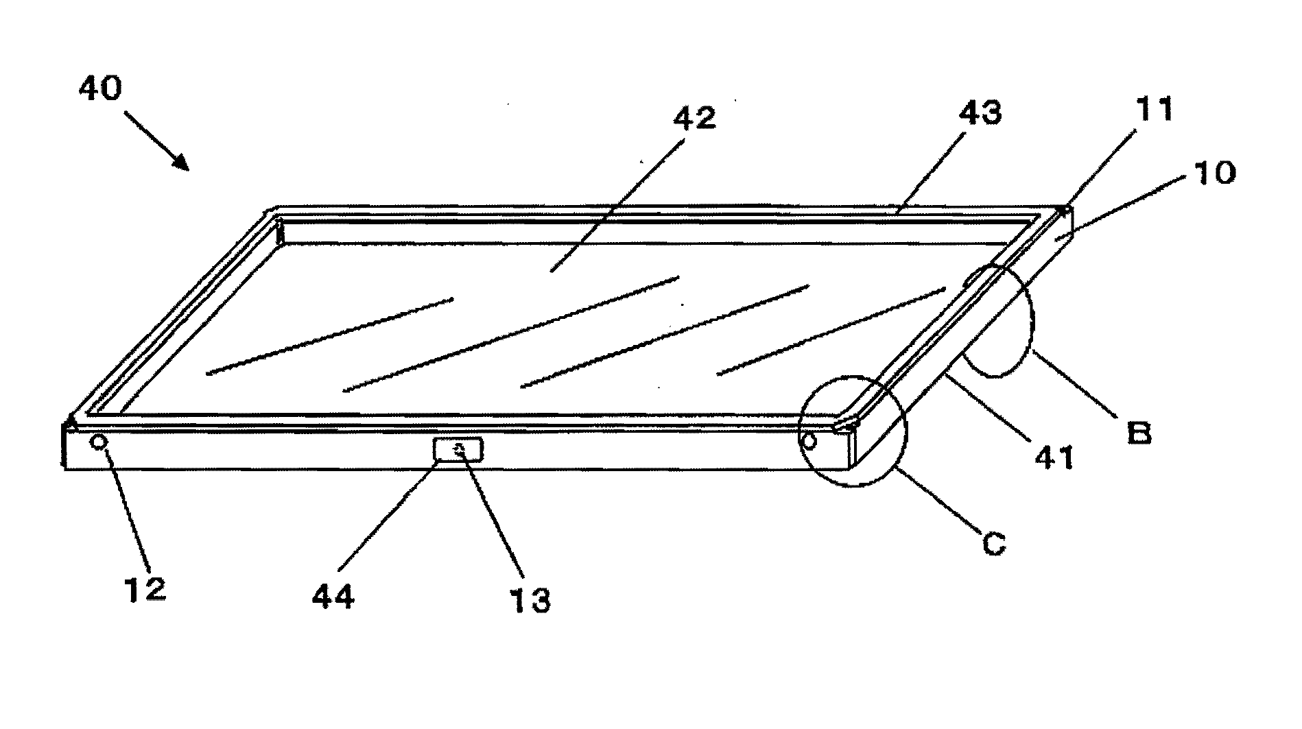
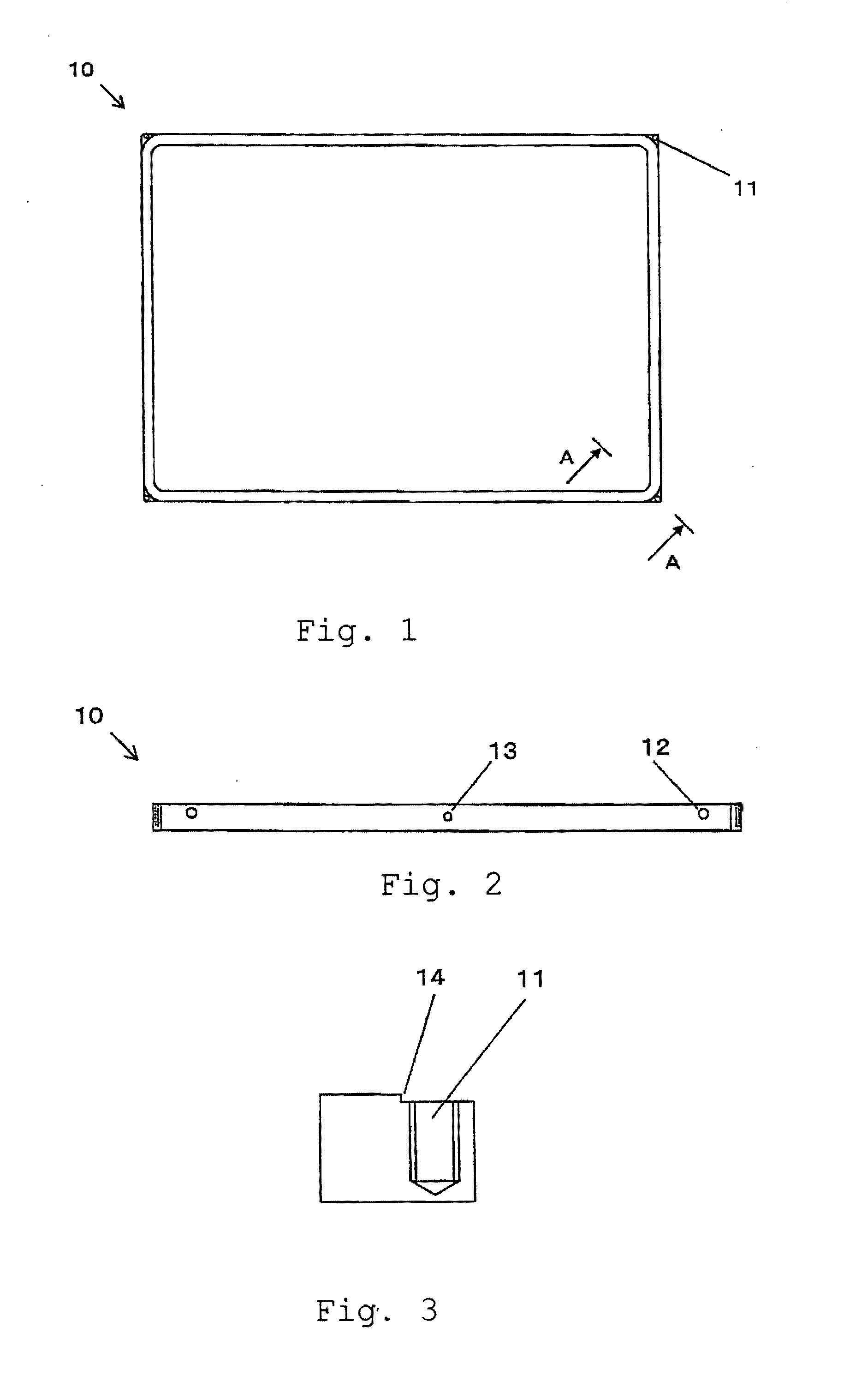
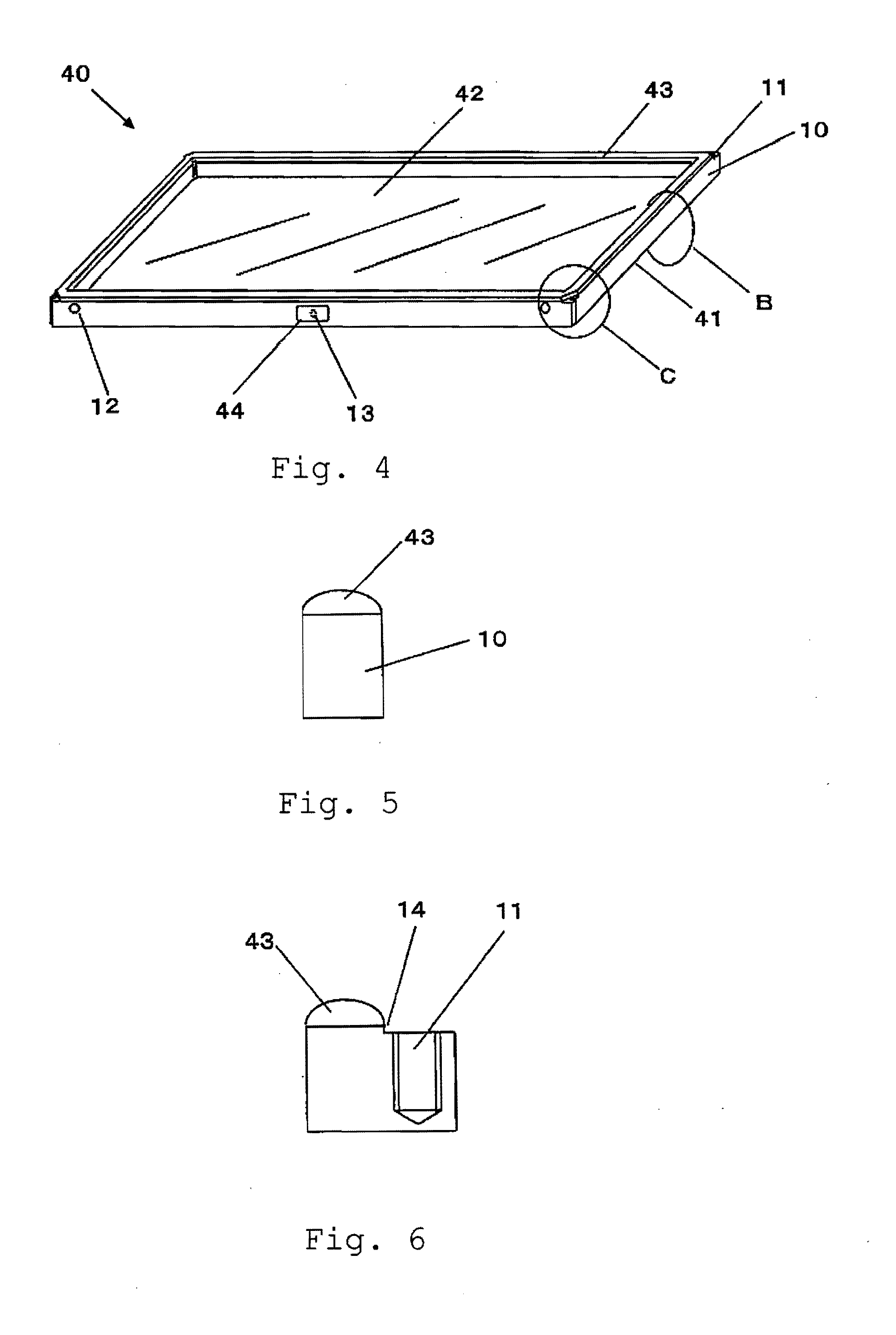
[0060]Next, we will explain about an example of the present invention, and in this example, a pellicle frame 10 having an appearance as indicated in FIG. 1 and FIG. 2 was manufactured by machining. This rectangular pellicle frame 10 had an external dimension of 115 mm×149 mm, an internal dimension of 111 mm×145 mm, and a height of 3.5 mm. The flatness of the pellicle was 20 micrometers, and jig holes 12 were made in the outer wall of each one of the longer-side pellicle frame bars for handling operation, and penetrating vent hole 13 was made through each one of the longer-side pellicle frame bars. The pellicle frame 20 was made of an aluminum alloy A7075, and after the machining a black color alumite treatment was applied to the frame surface. Each corner of this pellicle frame 10 was formed with a step 14 having a height of 0.15+ / −0.01 mm, as shown in FIG. 3, and was formed with a non-penetrating female screw 11 having a diameter of 1 mm and a pitch of 0.2 mm, the screw 11 being lo...


PUM


Abstract

A pellicle was well as an assembly of photomask plus pellicle is proposed in which the conventional agglutinant layer which bonds the pellicle to photomask is replaced by male and female screws and elastic body layer; in particular the pellicle frame is screwed to the photomask while the sealing of the space within the pellicle frame is secured by the elastic body layer.

Description

[0001]The present non-provisional patent application claims priority, as per Paris Convention, from Japanese Patent Application No. 2013-89101 filed on Apr. 22, 2013, the disclosure of which is hereby incorporated by reference herein in its entirety.FIELD OF THE INVENTION[0002]The present invention relates to a pellicle useful as a dust-fender employed in the scenes of manufacturing semiconductor devices, IC packages, printed circuit boards, liquid crystal display panels, organic EL display panels, etc., and also to an assembly of a photomask with such a pellicle.BACKGROUND TECHNOLOGY[0003]In manufacturing semiconductor devices such as LSI and super-LSI or in manufacturing a liquid crystal display panel or the like, a pattern is made by irradiating a ultraviolet light to a semiconductor wafer or a glass plate for liquid crystal, but if a dust particle is sticking to a photomask used in this stage, the dust particle obstructs the light or reflects it, causing deformation, short circu...

Claims


Application Information

Patent Timeline
IPC IPC(8): G03F1/64G03F1/22
CPCG03F1/22G03F1/64Y10T428/24008G03F1/62
Inventor SEKIHARA, KAZUTOSHI
Owner SHIN ETSU CHEM IND CO LTD
Learn More