
Process control of an industrial plant

a technology of industrial plant and process control, applied in the direction of electric controller, program control, electric programme control, etc., can solve the problems of reducing the life of the operating components of the plant, reducing the efficiency of operation, and reducing the quality of products

Active Publication Date: 2014-10-23
AUCKLAND UNISERVICES LTD
View PDF6 Cites 36 Cited by
  • Summary
  • Abstract
  • Description
  • Claims
  • Application Information

AI Technical Summary

Benefits of technology

This patent is about a system and method for controlling a plant's operation to reduce variations in key process variables. The system can identify abnormal patterns of variation that may be caused by a single dominant cause, and can correct or minimize these causes to improve the plant's performance and reliability. The method combines automatic control with continuous improvement, and can also provide an early warning of potential operational issues using a complexity measure. Overall, this patent aims to optimize the plant's operation and increase its stability and reliability.

Problems solved by technology

This has resulted in reduction in the lives of operating components of the plant, reduced operating efficiencies and reduction in product quality.
Furthermore, the flexibility of pot line electricity usage is an increasingly important issue for smelters because of country and continental electricity grids and variation in availability and price which connection to such grids can impose.
A problem with this approach is that this may produce greater variation over time and compound the initial causes of the variation.
In fact, the initial causes of the variation may not be addressed at all due to the reliance on manipulation of control inputs not necessarily related to the cause, allowing the causes of the variation to remain embedded in the process and increase in number over time.
With the above arrangements, inadequate information is provided to enable comprehensive operational or automatic control of the smelting operation to be effected.

Method used


Image

  • Process control of an industrial plant
  • Process control of an industrial plant
  • Process control of an industrial plant

Examples


Embodiment Construction

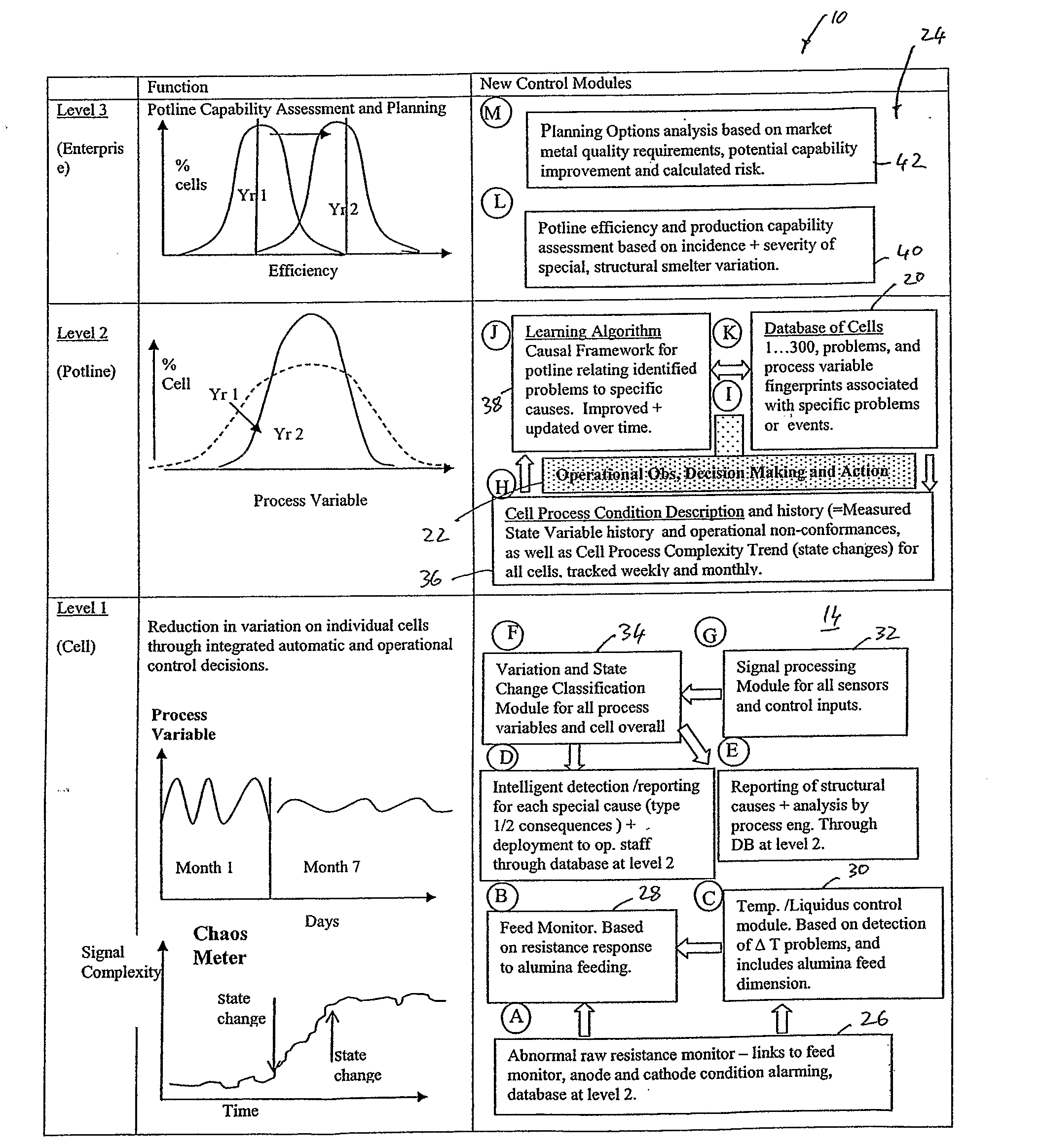
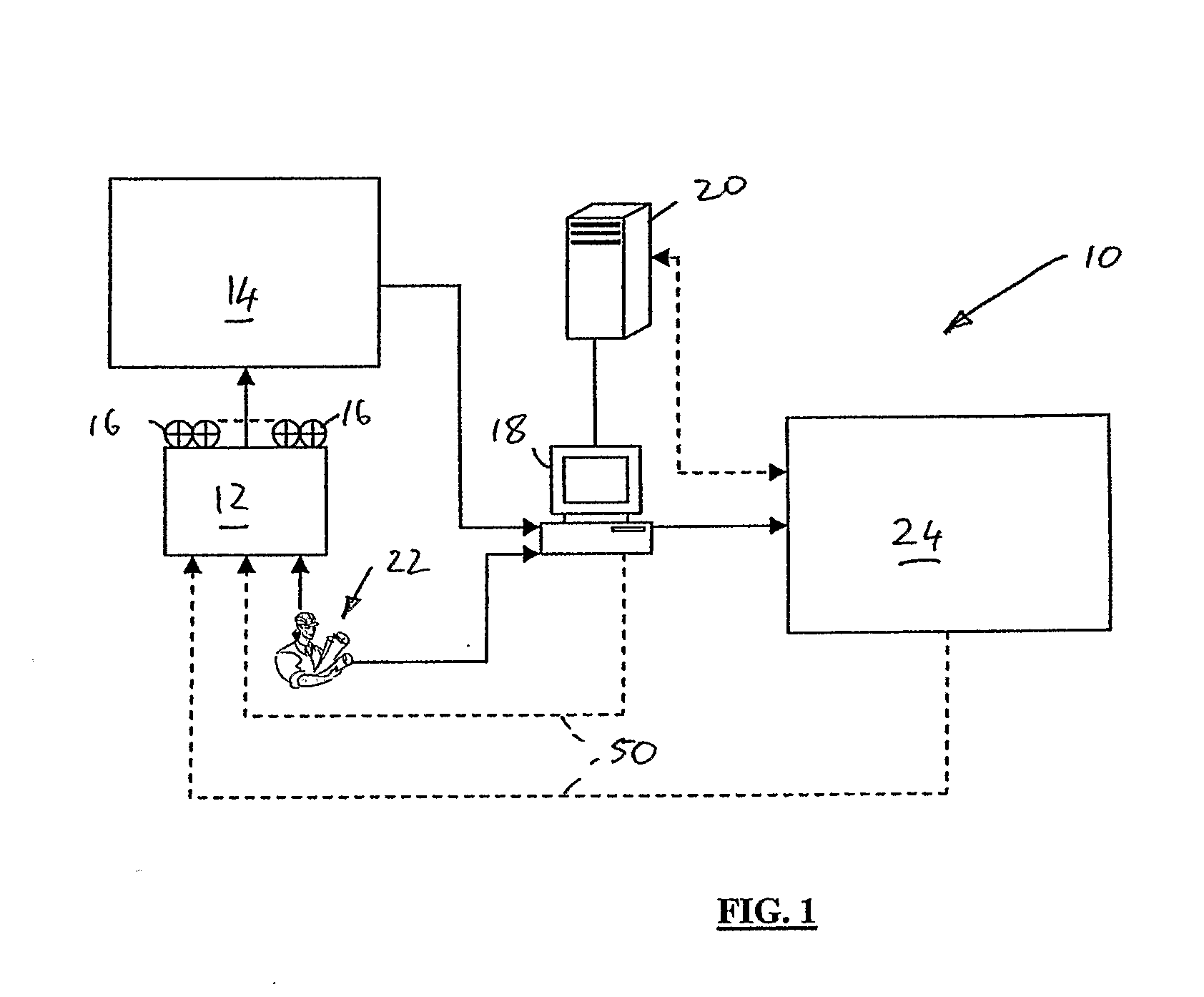
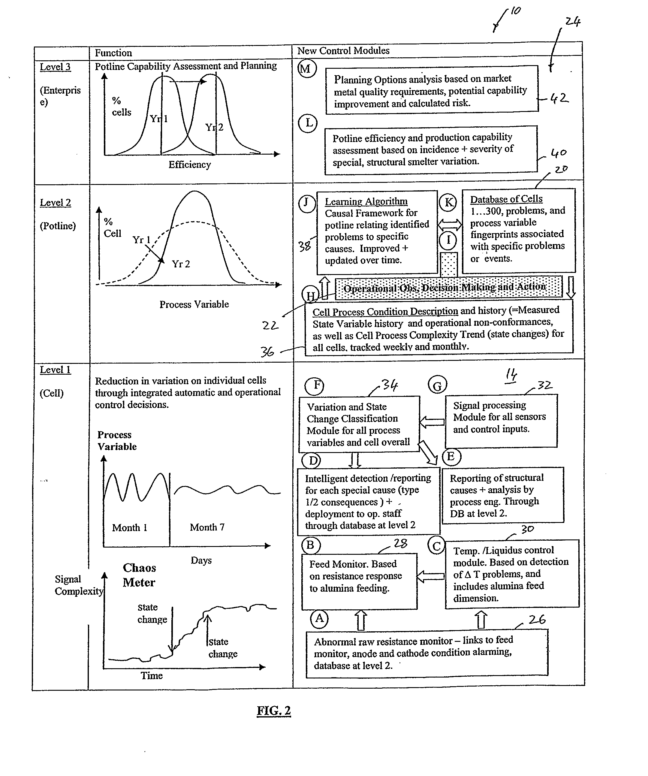
[0123]In FIG. 1 of the drawings reference numeral 10 generally designates a system, in accordance with an embodiment of the invention, for controlling an industrial plant. The plant is designated generally by the reference numeral 12. The system 10 will be described with reference to its application to an aluminium smelting operation but it will be appreciated that the system 10 could be used in any industrial plant requiring control. The smelting operation or smelter 12 comprises a plurality of pot lines. Each pot line is constituted by a plurality of cells in which alumina is processed to form aluminium. Aluminium formed in the cells is tapped off periodically for casting or further processing downstream in the plant 12.

[0124]The purpose of the system 10 is to minimize energy consumption and smelter emissions, maximize productivity and metal purity and promote a safer, healthier working environment over time by continuously reducing and removing variations in the process. The cont...


PUM

PropertyMeasurementUnit
timeaaaaaaaaaa
thicknessaaaaaaaaaa
heightaaaaaaaaaa

Abstract

A system 10 for controlling an industrial plant 12 comprises automatic control equipment 14 comprising a plurality of measurement sensors 16 for sensing predetermined variables associated with components of the industrial plant 12. The sensors 16 generate measured data relating to operation of the components of the industrial plant 12. A database 20 contains operational data, including observational data, regarding the industrial plant 12. A processor 18 is in communication with the automatic control equipment 14 and the database 20 for receiving the measured data from the sensors 16 of the automatic control equipment 14 and the operational data from the database 20. The processor 18 manipulates the measured and operational data to provide an evolving description of a process condition of each component over time, along with output information relating to operational control of the industrial plant 12 and for updating the database 20.

Description

CROSS-REFERENCE TO RELATED APPLICATIONS[0001]The present application claims priority from Australian Provisional Patent Application No 2006904359 filed on 9 Aug. 2006, the contents of which are incorporated herein by reference.FIELD OF THE INVENTION[0002]This invention relates to process control of an industrial plant. More particularly, the invention relates to a system for, and a method of, controlling an industrial plant particularly, but not necessarily exclusively, a smelting plant.BACKGROUND TO THE INVENTION[0003]The present demand for an increasingly rapid financial return in industrial plants such as smelting operations has driven operating parameters beyond their current performance limits. This has resulted in reduction in the lives of operating components of the plant, reduced operating efficiencies and reduction in product quality. The ever present need to reduce carbon and / or other greenhouse gas emissions is adding additional pressure to the situation. In the case of s...

Claims


Application Information

Patent Timeline
Patent Type & Authority Applications(United States)
IPC IPC(8): G05B19/418G05B11/01
CPCG05B19/41835G05B2219/32009G05B11/01C25C3/06C25C3/20G05B2219/31455G05B23/0294
Inventor TAYLOR, MARK P.CHEN, JOHN J.J.
Owner AUCKLAND UNISERVICES LTD
Learn More