Fluid cooled lances for top submerged injection

a technology of injecting lances and fluid cooled lances, which is applied in the direction of manufacturing converters, furnaces, charge manipulation, etc., can solve the problems of increasing the flow velocity of coolant fluid between the end wall and the outlet end of the intermediate, and achieves the effect of increasing the flow velocity of coolant fluid

Active Publication Date: 2014-11-06
METSO OUTOTEC (FINLAND) OY
View PDF4 Cites 13 Cited by
  • Summary
  • Abstract
  • Description
  • Claims
  • Application Information

AI Technical Summary

Benefits of technology

[0031]In a first aspect, the present invention provides a lance for top submerged lancing injection within a slag layer of a molten bath, wherein the lance has an outer shell of three substantially concentric lance pipes and, at least one further lance pipe included and arranged substantially concentrically within the shell. At an outlet end of the lance, there is an annular end wall which joins the respective end of the outermost and innermost lance pipes of the shell at an outlet end of the lance and is spaced from the outlet end of the intermediate lance pipe of the shell. The arrangement is such that coolant fluid is able to be circulated through the shell of the lance, such as along the shell to the outlet end by flow between the innermost and intermediate lance pipes of the shell and then back along the lance, away from the outlet end, by flow between th

Problems solved by technology

However, the spacing between that outlet end and the end wall is such as to provide a constriction to flow of the coolant fluid which causes an increase in the coolant fluid flow velocity across and between the end wall and the outlet end of the intermediate lance pipe.
However, unlike an arrangement in whi

Method used


Image

  • Fluid cooled lances for top submerged injection
  • Fluid cooled lances for top submerged injection
  • Fluid cooled lances for top submerged injection

Examples


Embodiment Construction

[0056]In order that the invention may more readily be understood, reference now is directed to the accompanying drawings, in which:

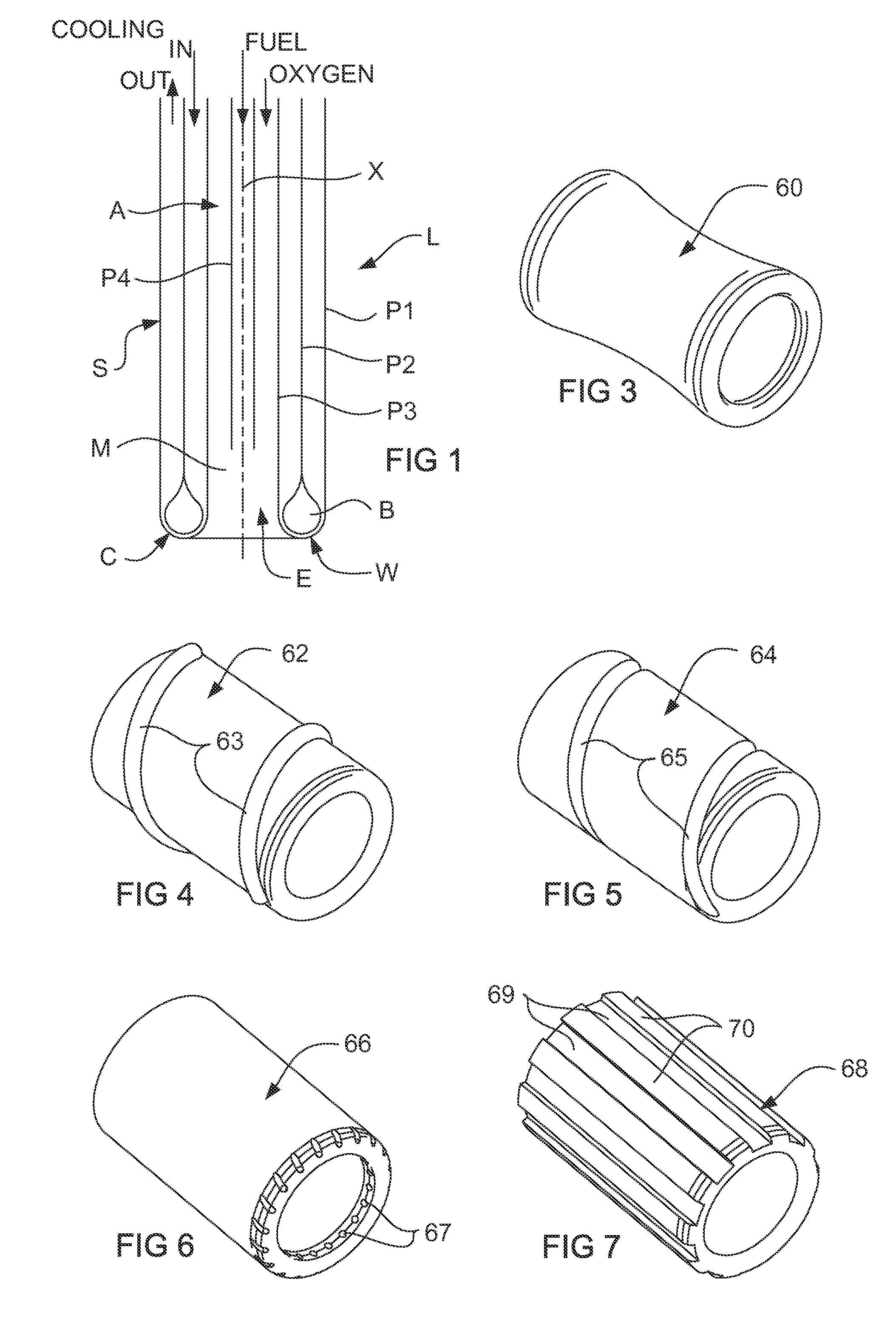
[0057]FIG. 1 is a schematic representation of one form of a lance according to the present invention;

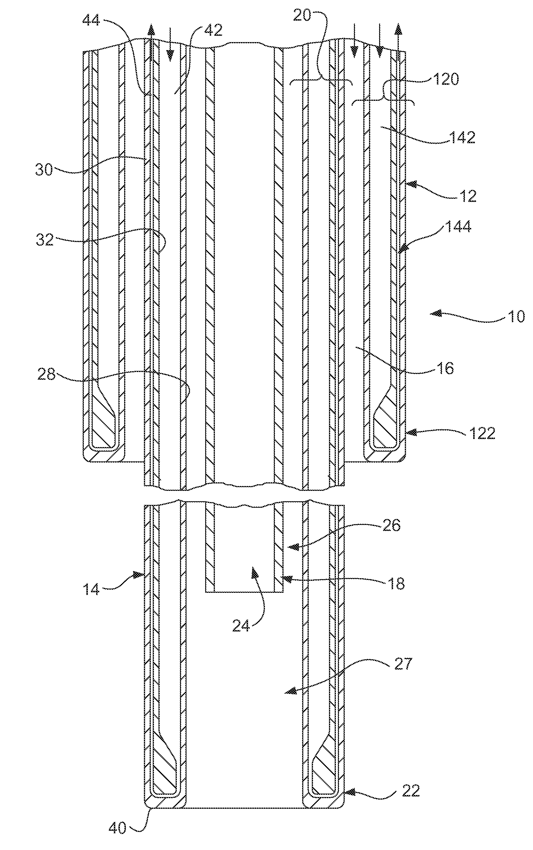
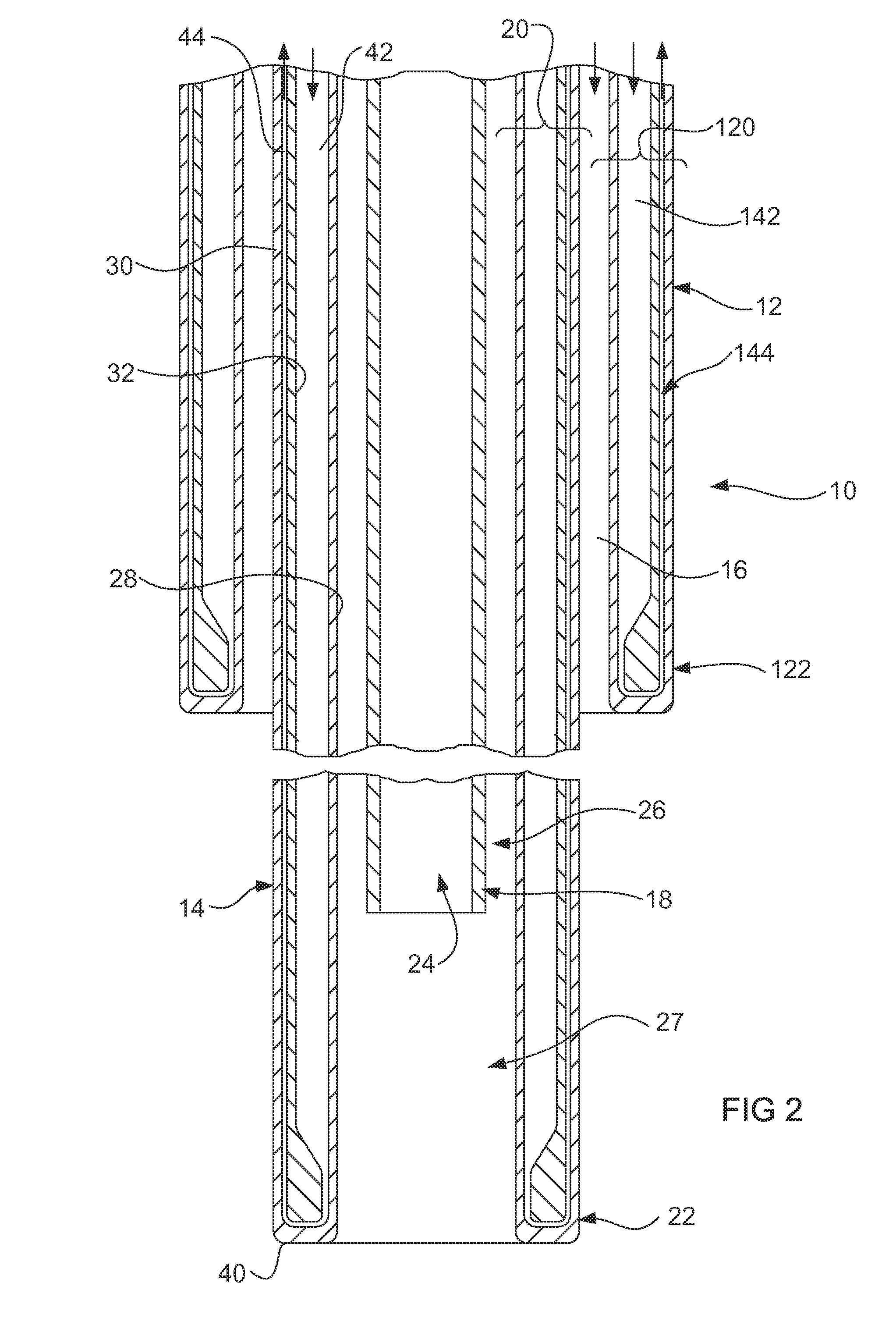
[0058]FIG. 2 is a sectional view of the lower part of a shrouded lance assembly according to the present invention; and

[0059]FIGS. 3 to 7 show respective perspective views of alternative forms for a component of the shrouded lance assembly of FIG. 2.

[0060]FIG. 1 schematically illustrates a TSL lance L according to one embodiment of the present invention. The lance L has four concentric pipes P1 to P4 of which pipes P1 to P3 form the main part of a shell S which also includes an annular end wall W. In the illustrated arrangement the lance L enables top submerged injection within the slag layer of a molten bath, for a required pyrometallurgical process, by injection of fuel down the bore of pipe P4 and injection of air and / or oxygen down through the annular...


PUM

PropertyMeasurementUnit
Angleaaaaaaaaaa
Angleaaaaaaaaaa
Angleaaaaaaaaaa

Abstract

A TSL lance has an outer shell of three substantially concentric lance pipes, at least one further lance pipe concentrically within the shell, and an annular end wall at an outlet end of the lance which joins ends of outermost and innermost lance pipes of the shell at an outlet end of the lance and is spaced from an outlet end of the intermediate lance pipe of the shell. Coolant fluid is able to be circulated through the shell, by flow to and away from the outlet end. The spacing between the end wall and the outlet end of the intermediate pipe provides a constriction to the flow of coolant fluid to increase coolant fluid flow velocity therebetween. The further lance pipe defines a central bore and is spaced from the innermost lance pipe of the shell to define an annular passage, whereby materials passing along the bore and the passage mix adjacent to the outlet end of the lance. The end wall and an adjacent minor part of the length of the shell comprise a replaceable lance tip assembly.

Description

FIELD OF THE INVENTION[0001]This invention relates to top submerged injecting lances for use in molten bath pyrometallurgical operations.BACKGROUND TO THE INVENTION[0002]Molten bath smelting or other pyrometallurgical operations which require interaction between the bath and a source of oxygen-containing gas utilize several different arrangements for the supply of the gas. In general, these operations involve direct injection into molten matte / metal. This may be by bottom blowing tuyeres as in a Bessemer type of furnace or side blowing tuyeres as in a Peirce-Smith type of converter. Alternatively, the injection of gas may be by means of a lance to provide either top blowing or submerged injection. Examples of top blowing lance injection are the KALDO and BOP steel making plants in which pure oxygen is blown from above the bath to produce steel from molten iron. Another example of top Mitsubishi copper process, in which injection lances cause jets of oxygen-containing blowing lance i...

Claims


Application Information

Patent Timeline
IPC IPC(8): F27D3/16
CPCF27D3/16F27D2009/0067F27D2003/169F27D2003/164C21C5/4613F27D3/18C21C2005/4626
Inventor MATUSEWICZ, ROBERTREUTER, MARKUS
Owner METSO OUTOTEC (FINLAND) OY
Why Eureka
Try Eureka