Dynamic Field Camera Arrangement for Magnetic Resonance Applications and Methods for Operating the Same

Active Publication Date: 2014-11-06
EIDGENOSSISCHE TECHN HOCHSCHULE ETH +1
View PDF8 Cites 7 Cited by
  • Summary
  • Abstract
  • Description
  • Claims
  • Application Information

AI Technical Summary

Benefits of technology

The patent is about a field camera arrangement for an MRI machine that detects both magnetic field and acoustic signals. By using microphones and a suitable calibration measurement, the MRI machine can assess the delay of the acoustic signal receive path and adjust the time axes of both the RF detector set and the low-frequency magnetic field detector set. This information can be used to improve the comfort of the patient and develop new MRI hardware or sequences. Additionally, the patent discusses the use of hexafluoro-2-propanol, which has favorable T1 / T2 ratios for short relaxation times, and the use of solubilizers to achieve more pronounced shifts and / or relaxation time changes. The patent also mentions the need for a calibration to synchronize the time axes of the MRI machine with the dynamic field camera.

Problems solved by technology

A shortcoming of the magnetic field camera and monitoring arrangements and methods used so far is caused by the fact that in order to avoid unacceptable interference with the principal measurement and / or damage of certain components the field probe data acquisition is limited to certain time windows of the principal measurement, where no radio-frequency (RF) excitation pulse is played out.
An additional drawback is the fact that in general the sequence of pulses used to excite the NMR field probes is generally not synchronized to the pulse sequence of the principal measurement; consequently the field probe excitation pulses might occur at any time during the actual MR sequence.

Method used


Image

  • Dynamic Field Camera Arrangement for Magnetic Resonance Applications and Methods for Operating the Same
  • Dynamic Field Camera Arrangement for Magnetic Resonance Applications and Methods for Operating the Same
  • Dynamic Field Camera Arrangement for Magnetic Resonance Applications and Methods for Operating the Same

Examples


Embodiment Construction

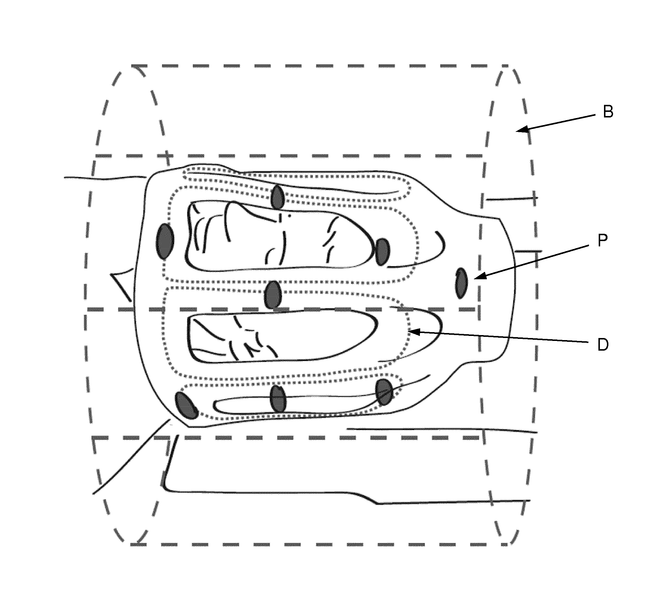
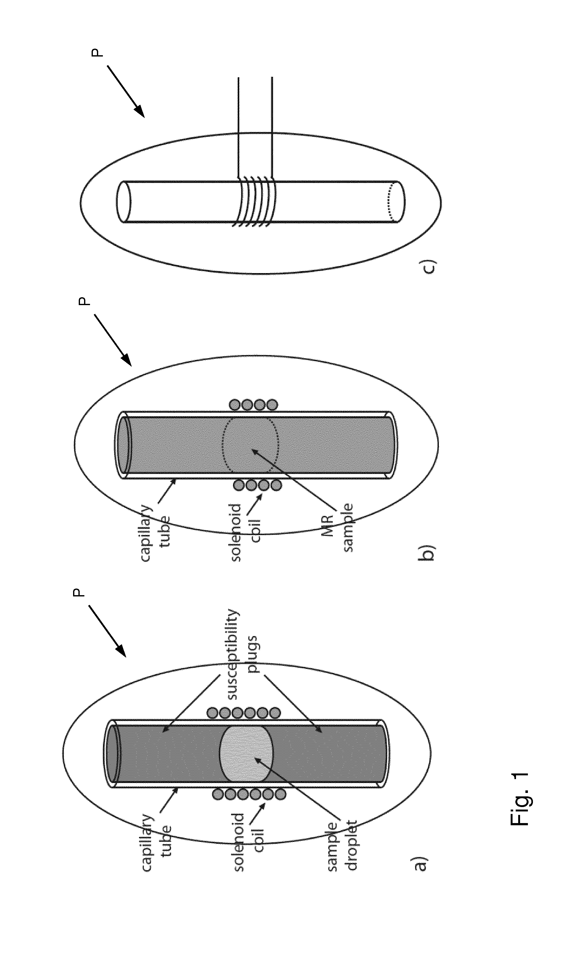
[0082]The low-frequency magnetic field detectors, also called “probes” P, shown in FIGS. 1a to 1c each comprise a magnetic resonance (MR) active substance, which in most cases is in liquid form. As mentioned further above, the magnetic field detectors are intended for monitoring electromagnetic field behavior in a spatial region comprising a main magnetic field (B0) and a radiofrequency (RF) field limited to a first RF band, particularly in an MRI or NMR apparatus. Each detector has means for pulsed MR excitation of said substance and means for receiving an MR signal generated by said substance, realized here as one solenoid coil wound around a capillary tube serving as container for the MR active substance. It is understood that the excitation and receiving means comprise further components not shown in these drawings, particularly electronic components for generating the RF excitation pulse and other electronic components for receiving and processing the probe signal. It is also u...


PUM


Abstract

A dynamic field camera arrangement for monitoring electromagnetic field behavior in a spatial region comprises a main magnetic field and a radiofrequency (RF) field limited to a first RF band, particularly in an MRI or NMR apparatus. The arrangement comprises a magnetic field detector set comprising a plurality of low-frequency magnetic field detectors, each one of said magnetic field detectors comprising a magnetic resonance (MR) active substance, means for pulsed MR excitation of said substance and means for receiving an MR signal generated by said substance, wherein said pulsed excitation and said MR detector signal is in a second RF band that does not overlap said first RF band. The MR signal receiving means comprise a first RF filter which suppresses RF signal from said first RF band and transmits RF signal from said second RF band.

Description

FIELD OF THE INVENTION[0001]The present invention generally relates to a dynamic field camera arrangement for magnetic resonance applications and to methods of operating the same.BACKGROUND OF THE INVENTION[0002]An important requirement for high quality magnetic resonance (MR) applications such as nuclear magnetic resonance (NMR) spectroscopy and magnetic resonance imaging (MRI) is to have accurate information about the spatio-temporal electromagnetic field evolution during the various measurements.[0003]It has long been recognized that the spatiotemporal low-frequency magnetic field evolution in a volume of interest can be determined by means of an array comprising a plurality of magnetic field probes arranged within or in the vicinity of the volume of interest (Barmet et al. ISMRM 2009 p. 780). Such arrangements are occasionally referred to as “dynamic magnetic field cameras”. It allows for observing the spatiotemporal low-frequency magnetic field evolution with the full bandwidth...

Claims


Application Information

Patent Timeline
IPC IPC(8): G01R33/36G01R33/24
CPCG01R33/3607G01R33/246G01R33/24G01R33/243G01R33/281G01R33/3657G01R33/58
Inventor BARMET, CHRISTOPHBRUNNER, DAVIDWILM, BERTRAMPRUSSMANN, KLAAS
Owner EIDGENOSSISCHE TECHN HOCHSCHULE ETH
Why Eureka
Try Eureka