Polymer-based resonator antennas

a resonator body and polymer technology, applied in the field of radio frequency (rf) antennas, can solve the problems of limiting the wider use of dras, dras have been mostly limited to simple structures, and the fabrication process of ceramic-based dras is more complex and costly, so as to improve the effect of the relative permittivity of the polymer-based resonator body

Active Publication Date: 2014-11-06
UNIVERSITY OF SASKATCHEWAN +1
View PDF17 Cites 45 Cited by
  • Summary
  • Abstract
  • Description
  • Claims
  • Application Information

AI Technical Summary

Benefits of technology

[0042]In a further broad aspect, there is provided a dielectric resonator antenna comprising: a substrate with at least a first planar surface; a polymer-based resonator body; and an excitation structure for exciting the polymer-based resonator body, wherein the polymer-based resonator body comprises a plurality of metal inclusions extending through the polymer-based resonator body in a direction generally perpendicular to the substrate, and wherein the plurality of metal inclusions are provided in a regular pattern to enhance an effective relative permittivity of the polymer-based resonator body.

Problems solved by technology

By comparison, ceramic-based DRAs can involve a more complex and costly fabrication process due in part to their three-dimensional structure and in part due to the difficulty of working with the ceramic materials.
These fabrication difficulties limit the wider use of DRAs, especially for high volume commercial applications.
In addition, while microstrip patch antennas can easily be produced in various complicated shapes by lithographic processes, DRAs have been mostly limited to simple structures (such as rectangular and circular / cylindrical shapes),
Indeed, fabrication of known DRAs can be particularly challenging as they have traditionally been made of high relative permittivity ceramics, which are naturally hard and extremely difficult to machine.
Batch fabrication by machining can be difficult, as the hardness of ceramic materials can require diamond cutting tools, which can wear out relatively quickly due to the abrasive nature of the ceramic materials.
In addition, ceramics are generally sintered at high temperatures in the range of 900-2000° C., further complicating the fabrication process and possibly restricting the range of available materials for other elements of the DRA.
Array structures can be even more difficult to fabricate due to the requirement of individual element placement and bonding to the substrate.
Accordingly, they cannot easily be made using known automated manufacturing processes.
Further problems appear at millimetre-wave frequencies, where the dimensions of the DRA are reduced to the millimetre or sub-millimetre range, and manufacturing tolerances are reduced accordingly.
These fabrication difficulties have heretofore limited the wider use of DRAs, especially for high volume commercial applications.

Method used


Image

  • Polymer-based resonator antennas
  • Polymer-based resonator antennas
  • Polymer-based resonator antennas

Examples


Embodiment Construction

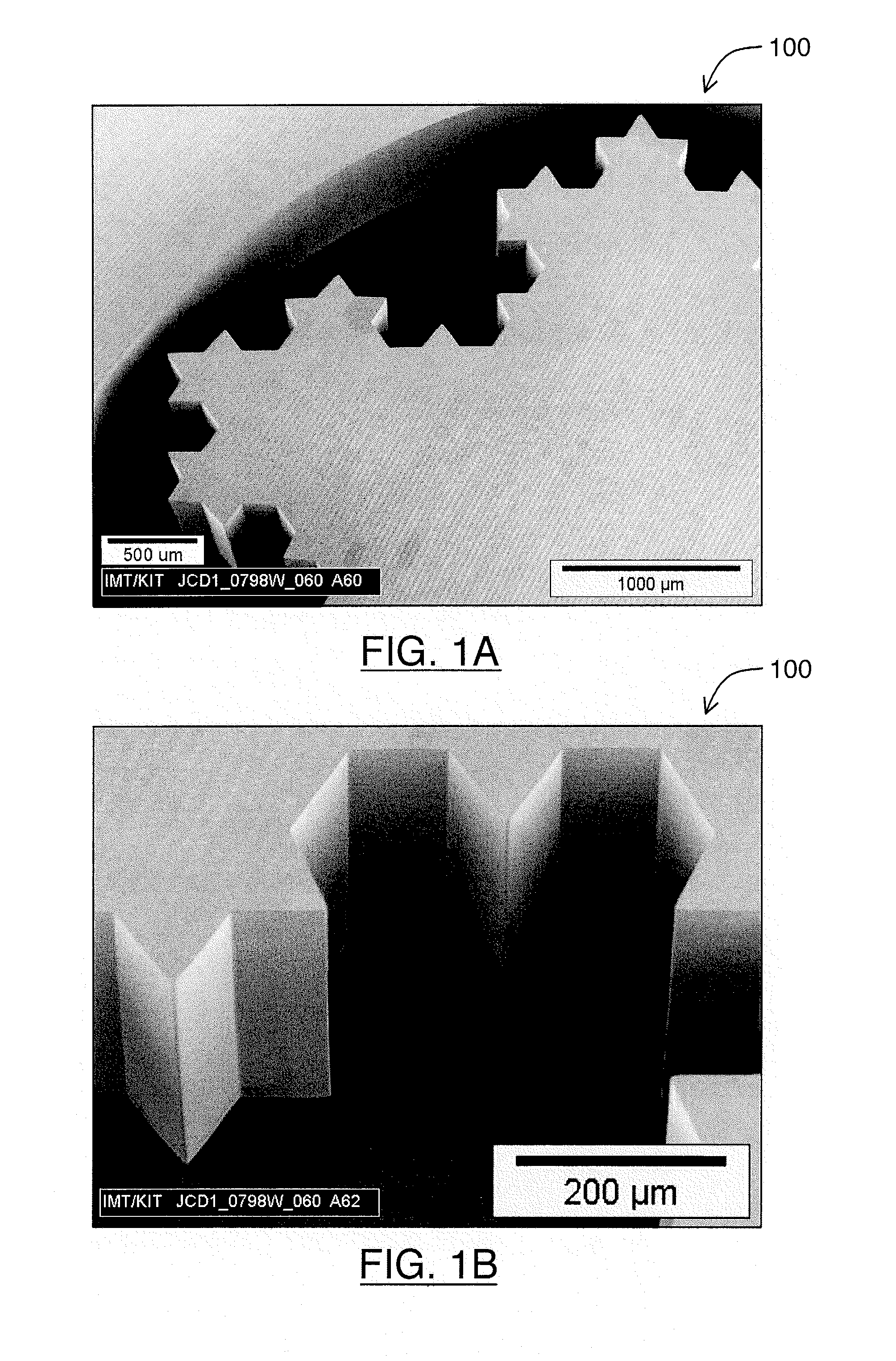
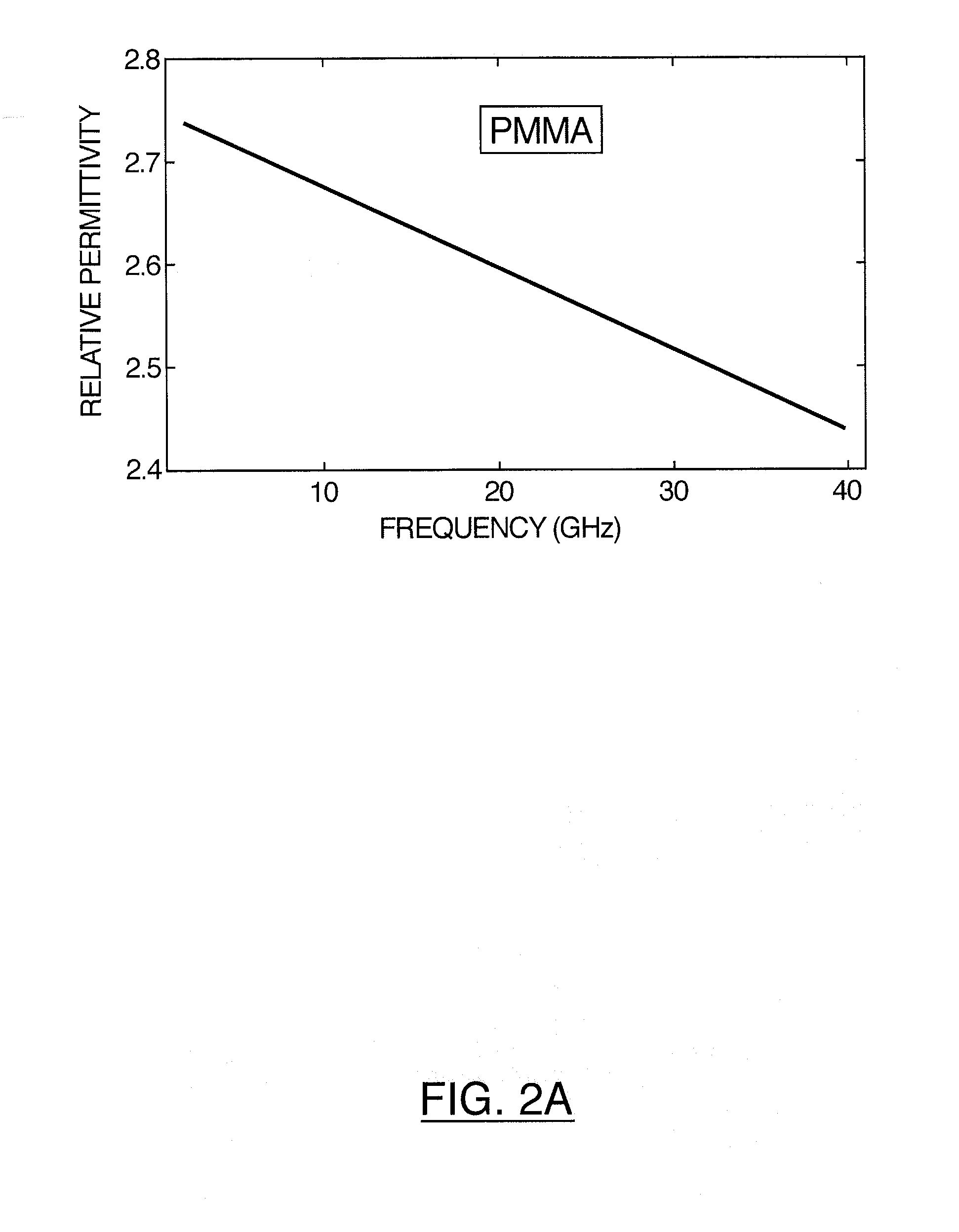
[0100]The use of polymer-based materials to fabricate DRAs may facilitate greater use of this class of antennas in commercial applications. The natural softness of polymers can dramatically simplify fabrication and their low relative permittivity can further enhance the impedance bandwidth of DRAs.

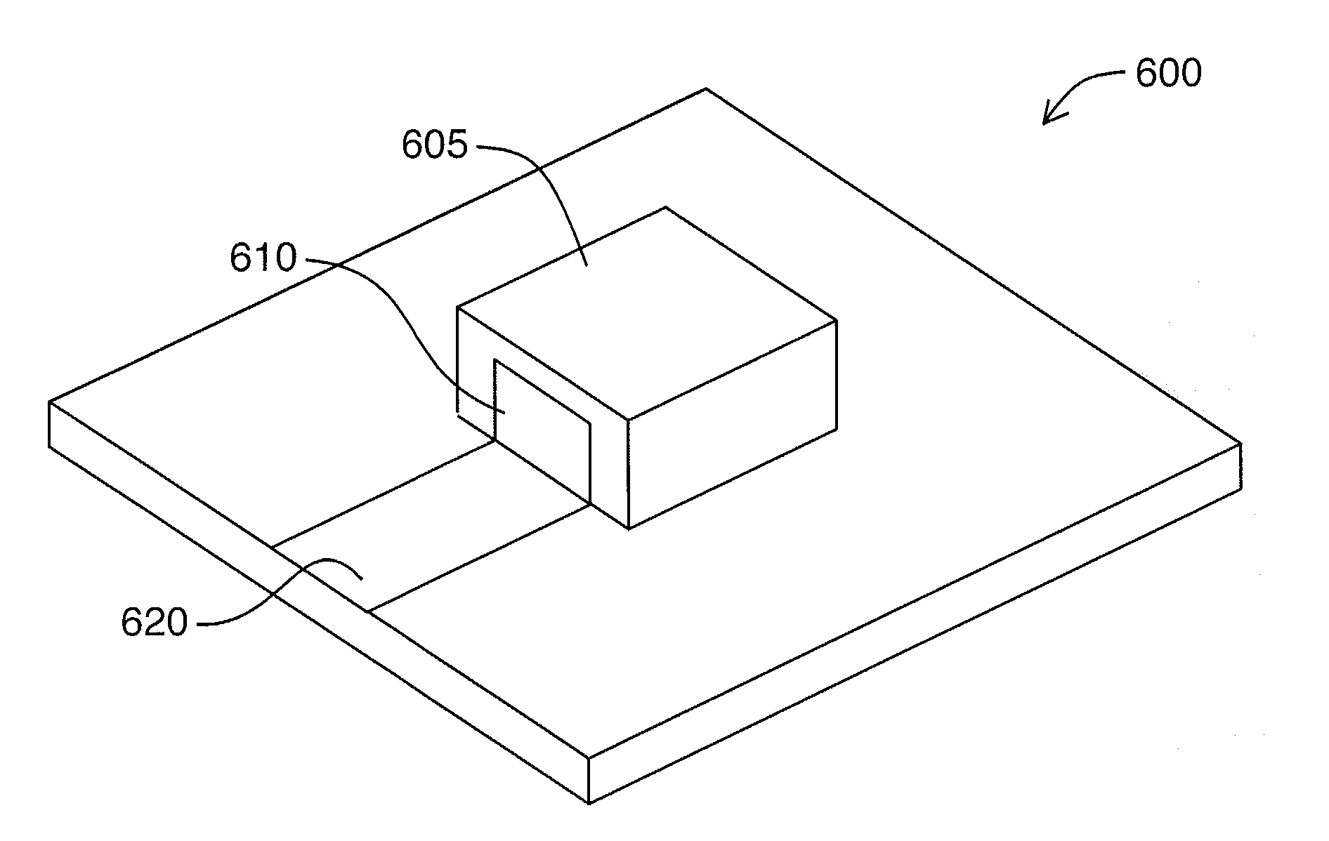
[0101]Described herein are compact radio frequency (RF) antennas and devices using non-traditional polymer-based materials, and methods for fabricating the same. The described compact RF antennas enable improved performance and increased functionality for various emerging wireless communication and sensor devices (e.g., miniature radios / transmitters, personal / wearable / embedded wireless devices, etc.), automotive radar systems, small satellites, RFID, sensors and sensor array networks, and bio-compatible wireless devices and biosensors). In particular, these polymer-based antenna devices may be referred to as polymer or polymer-based resonator antennas (PRAs).

[0102]Currently, one of the big...


PUM

PropertyMeasurementUnit
relative permittivityaaaaaaaaaa
temperaturesaaaaaaaaaa

Abstract

Dielectric resonator antennas suitable for use in compact radiofrequency (RF) antennas and devices, and methods of fabrication thereof. Described are dielectric resonator antennas fabricated using polymer-based materials, such as those commonly used in lithographic fabrication of integrated circuits and microsystems. Accordingly, lithographic fabrication techniques can be employed in fabrication. The polymer-based dielectric resonator antennas can be excited using tall metal vertical structures, which are also fabricated using techniques adapted from integrated circuit and microsystems fabrication.

Description

CROSS-REFERENCE TO RELATED APPLICATION[0001]This application claims the benefit of U.S. Provisional Application No. 61 / 513,354, filed Jul. 29, 2011. The entirety of U.S. Provisional Application No. 61 / 513,354 is hereby incorporated by reference.FIELD[0002]The embodiments described herein relate to radio frequency (RF) antennas and methods for fabricating the same. In particular, the described embodiments relate to dielectric resonator antennas.INTRODUCTION[0003]Contemporary integrated circuit antennas are often based on thin metallic microstrip “patch” structures, which can occupy large lateral areas. A microstrip antenna consists of a metallic strip or patch placed above a grounded substrate and generally fed through a coaxial probe or an aperture.[0004]Recently, dielectric resonator antennas (DRAs) have attracted increased attention for miniaturized wireless and sensor applications at microwave and millimetre-wave frequencies. DRAs are three-dimensional structures with lateral dim...

Claims


Application Information

Patent Timeline
Patent Type & Authority Applications(United States)
IPC IPC(8): H01Q9/04G03F7/40H01Q1/50
CPCH01Q9/0485G03F7/40H01Q1/50H01Q9/0492
Inventor RASHIDIAN, ATABAKKLYMYSHYN, DAVIDTAYFEH ALIGODARZ, MOHAMMADREZAACHENBACH, SVEN CARSTENBORNER, MARTIN WILFRIED
Owner UNIVERSITY OF SASKATCHEWAN
Why Eureka
Try Eureka