Waste heat recovery in a chemical process and plant, particularly for the synthesis of ammonia

a technology of ammonia and heat recovery, which is applied in the field of waste heat recovery in a chemical process and plant, can solve the problems of inconvenient recovery of low-temperature heat, inability to achieve high-temperature heat recovery, and inability to achieve high-temperature heat recovery, and achieves significant expansion ratio, value energy output, and improved overall efficiency of the process

Active Publication Date: 2014-11-13
CASALE SA
View PDF8 Cites 16 Cited by
  • Summary
  • Abstract
  • Description
  • Claims
  • Application Information

AI Technical Summary

Benefits of technology

[0028]The main advantage of the invention is that the waste heat is recovered in an efficient way, obtaining a valuable energy output. As a consequence, the overall efficiency of the process is improved. The use of ammonia as working fluid allows useful exploitation of the low-temperature heat, that would be unsuited, as stated above, for power generation via a steam turbine.
[0029]In fact, a low temperature heat source would only allow to produce saturated steam at a few bars pressure, which is not suited to efficient power generation via a steam turbine. In order to achieve a significant expansion ratio across the turbine, there would be the need of a low pressure output, resulting in a large flow rate and then in a large and expensive turbine stage. Moreover, due to poor inlet steam conditions, a steam turbine would also suffer the formation of condensate at the outlet, which is highly aggressive on the turbine blades. All the above drawbacks are overcome by use of the high-pressure ammonia as a working fluid.
[0030]Moreover, the invention also makes use of the significant pressure of the liquid product. Referring to the application to ammonia plants, in the prior art the pressure of the liquid ammonia stream is lowered through an expansion valve, which means that the pressure energy is lost. The invention provides efficient recovery of this pressure energy.
[0031]Another aspect of the invention is a plant adapted to carry out the above process. A plant according to the invention comprises a front-end section adapted to provide at least one make-up reactant, and a high-pressure synthesis section for reacting said at least one make-up reactant and obtaining a chemical product in a liquid state, the plant being characterized by comprising at least: a heat exchanger disposed to exchange heat between at least a portion of the liquid product delivered by the synthesis section, and a waste-heat source stream, obtaining an expandable stream of said product in a vapour state or supercritical state; an expander receiving said expandable stream and adapted to deliver mechanical energy produced by expansion of said stream, and a condenser downstream said expander, and disposed to condense the effluent of said expander.
[0032]According to embodiments of the invention, one or more heat exchanger(s), expander(s) and condenser(s) may be provided. According to the above disclosed preferred embodiments of the invention, the plant is preferably an ammonia plant,
[0033]Another aspect of the invention is a method for revamping a plant for the synthesis of a chemical product, especially ammonia, by recovering waste heat from the front-end section of the plant in accordance with the above process. A plant for producing ammonia, comprising a front-end reforming section adapted to provide a make-up ammonia or syngas, and a high-pressure synthesis loop delivering liquid ammonia, is revamped by the following: arranging a heat exchange for heating at least a portion of the liquid ammonia product, by means of heat exchange with at least one source of waste heat, so obtaining a stream of heated, high-pressure ammonia stream in a vapour or supercritical state; the provision of at least an expander and preferably of a generator connected to said expander, for the expansion of said ammonia and the production of energy from said waste heat; the provision of a condenser adapted to condense the ammonia effluent at the outlet of said expander.

Problems solved by technology

Heat available at a lower temperature is generally not suitable to produce energy and can be recovered e.g. by pre-heating some process stream(s).
In some cases, however, the recovery of low-temperature heat may not be economically convenient.
The low-temperature heat of the syngas effluent for example from the low-temperature shift reactor, however, is more difficult to recover.
The LTS reactor effluent has a relatively low temperature of around 200-220° C., and conversion into energy with a steam turbine is not attractive at such a low temperature.
In the known art, the heat recovered from the cooling of the LTS reactor effluent is used for re-generating the solution (e.g. amine-based) of the CO2-washing column; however this use is not efficient in terms of energy, and recent CO2-removal processes such as physical washing or passing the syngas through a PSA device, no longer require a significant heat input.
There are other potential sources of recoverable heat, e.g. the effluent from the methanator or the synthesis loop downstream the hot gas / gas exchanger, or the flue gas from the steam reformer which is generally sent to the stack at 150 to 300° C. However the prior art does not provide an effective way for full exploitation of these potential heat sources.

Method used


Image

  • Waste heat recovery in a chemical process and plant, particularly for the synthesis of ammonia
  • Waste heat recovery in a chemical process and plant, particularly for the synthesis of ammonia
  • Waste heat recovery in a chemical process and plant, particularly for the synthesis of ammonia

Examples


Embodiment Construction

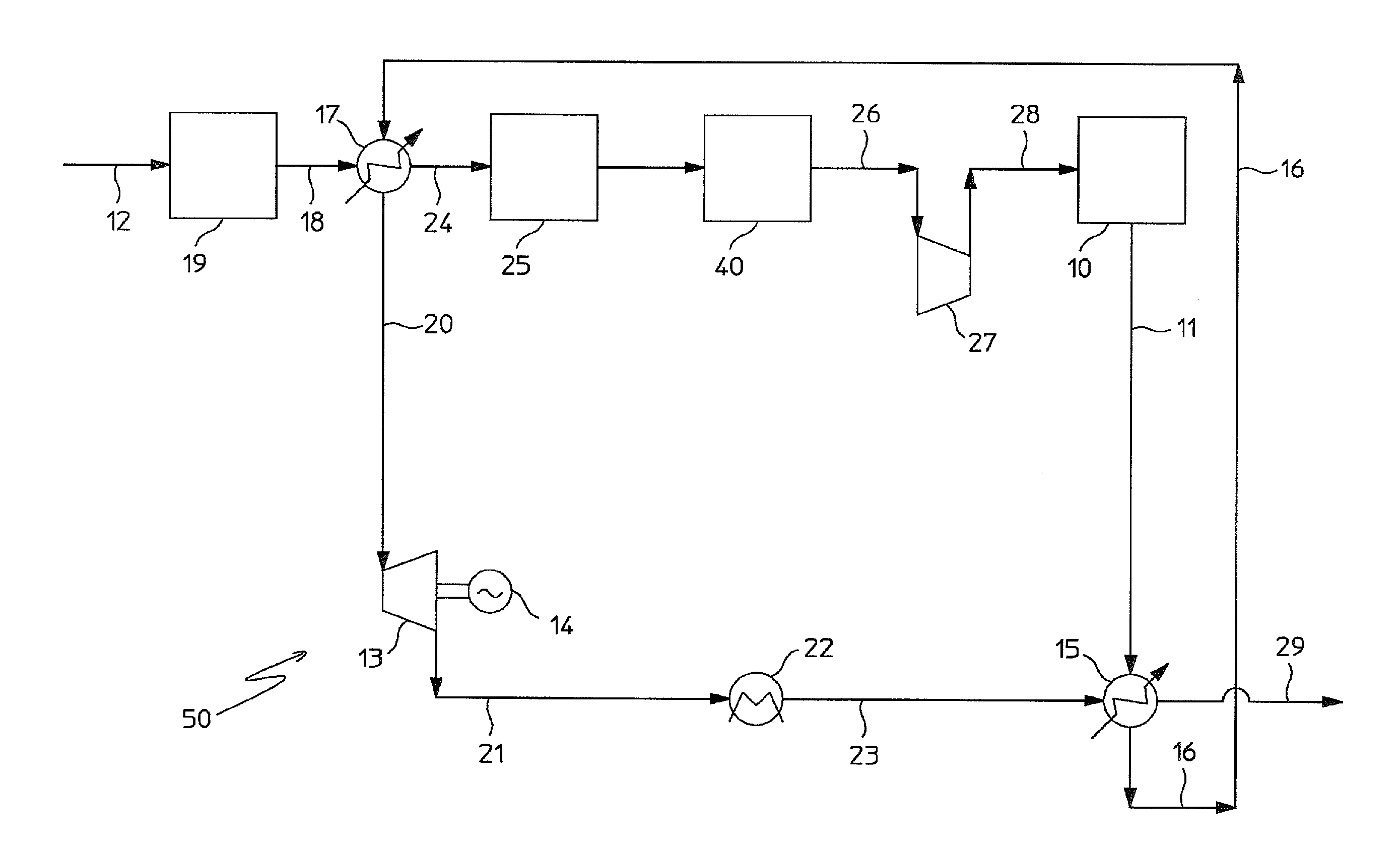
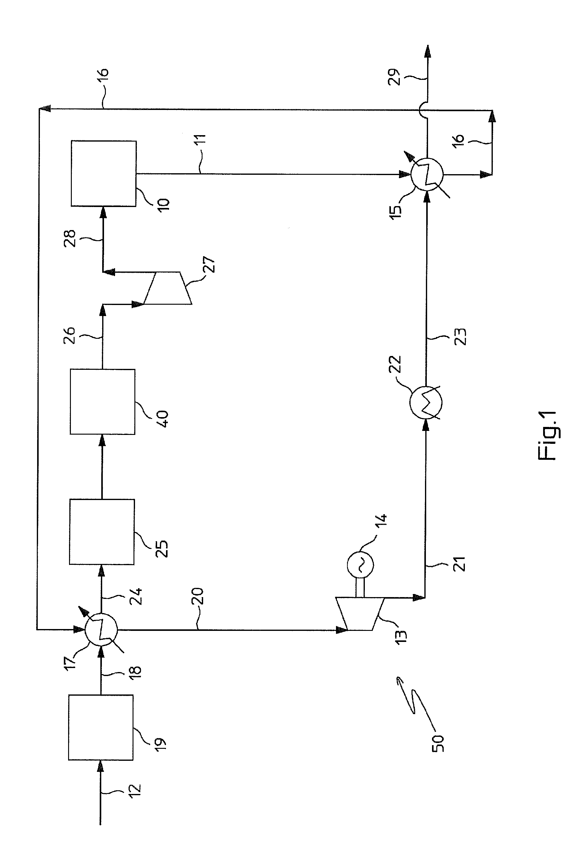
[0040]Referring to FIG. 1, a synthesis loop 10 delivers liquid ammonia 11 at a pressure of 80-300 bar and temperature around −30 to 10° C. The synthesis loop 10 is fed with a make-up synthesis gas which is produced in a front-end of the ammonia plant for example by steam reforming of natural gas or another suitable hydrocarbon.

[0041]The front-end may comprise a primary and a secondary reformer followed by a high-temperature and a low-temperature shift reactor. The LTS reactor is shown in FIG. 1 as 19. Downstream said LTS reactor, the make-up syngas passes in a CO2 removal unit 25; the CO2-free syngas 26 is further treated according to the needs, e.g. in a methanator, and then is fed to a main syngas compressor 27. The compressed syngas 28 is fed to the high-pressure synthesis loop 10, e.g. at a pressure of 150 bar.

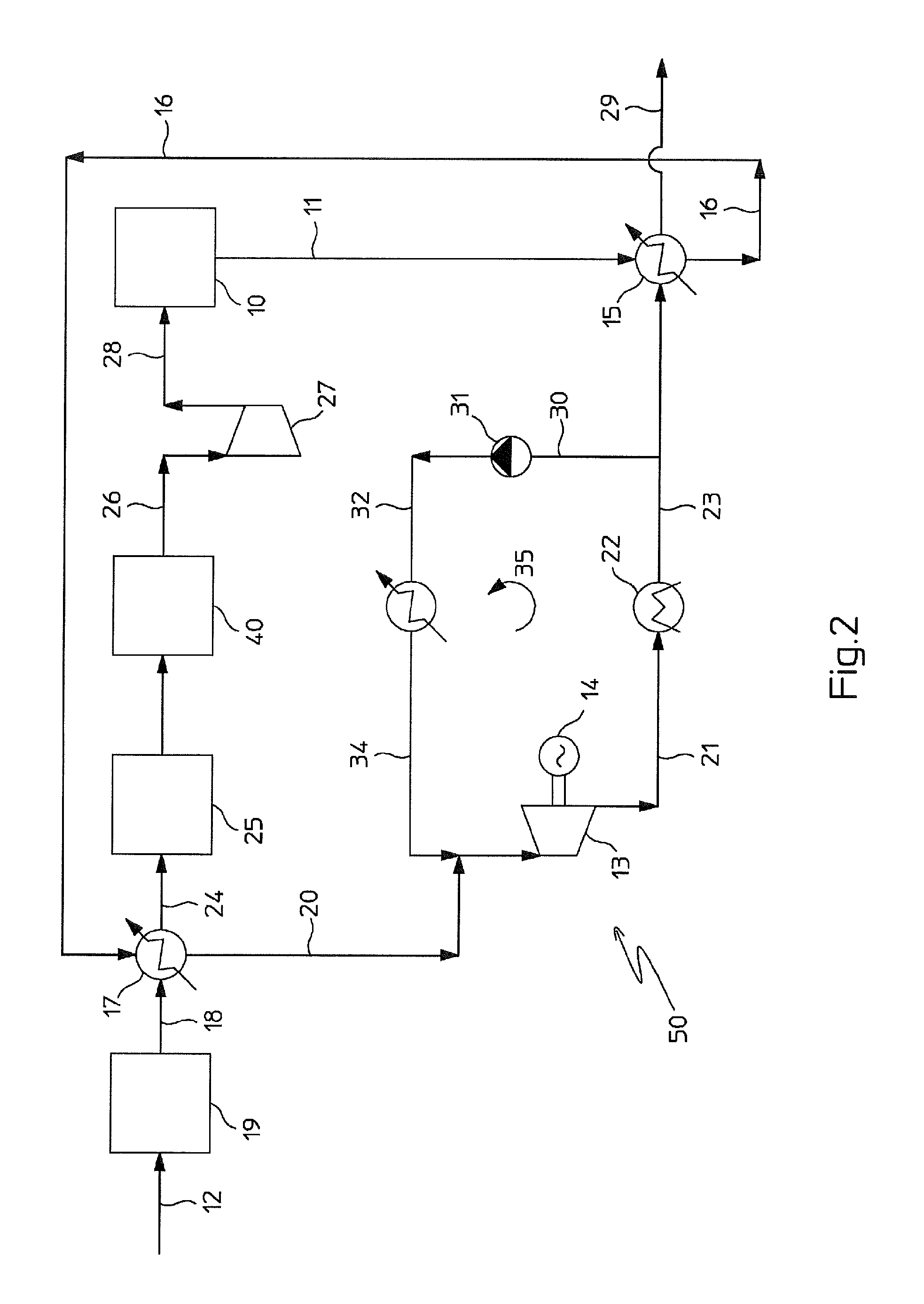
[0042]According to one of embodiments of the invention, the plant of FIG. 1 comprises an energy recovering section 50 operating with ammonia as working fluid, and recoveri...


PUM

PropertyMeasurementUnit
temperatureaaaaaaaaaa
pressureaaaaaaaaaa
temperatureaaaaaaaaaa

Abstract

A method for recovering waste heat in a process for the synthesis of a chemical product, particularly ammonia, where the product is used as the working fluid of a thermodynamic cycle; the waste heat is used to increase the enthalpy content of a high-pressure liquid stream of said product (11), delivered by a synthesis section (10), thus obtaining a vapour or supercritical product stream (20), and energy is recovered by expanding said vapour or supercritical stream across at least one suitable ex-pander (13); the method is particularly suited to recover the heat content of the syngas effluent after low-temperature shift.

Description

CROSS-REFERENCE TO RELATED APPLICATIONS[0001]This application is a continuation of U.S. patent application Ser. No. 13 / 388,793, filed Feb. 3, 2012, which is a national phase of PCT / EP2010 / 056750, filed May 17, 2010, which claims priority to European Patent Application No. 09169330.9, filed Sep. 3, 2009. The entire contents of these applications is incorporated herein by reference.FIELD OF THE INVENTION[0002]The present invention relates to waste heat recovery in a chemical process and plant. The invention is applicable for example to process and plants for the synthesis of ammonia.PRIOR ART[0003]Waste heat recovery is known in the art. In a chemical process, various waste heat sources can be available, e.g. from the cooling of intermediate product streams or flue gas of any combustion process. Heat available at a temperature of at least 400-500° C. is usually recovered by producing hot steam, which can be used in the process itself, or expanded in a turbine to produce energy. Heat a...

Claims


Application Information

Patent Timeline
Patent Type & Authority Applications(United States)
IPC IPC(8): F01K25/08
CPCF01K25/08C01B3/025C01B3/34C01B3/382C01B3/48C01B2203/0233C01B2203/0244C01B2203/0283C01B2203/0415C01B2203/0445C01B2203/0475C01B2203/068C01B2203/0811C01B2203/0833C01B2203/84C01C1/047C01C1/0488F01K25/106Y02P20/129Y02P20/52Y10T29/49716Y02E20/32Y02P20/10Y02P20/54
Inventor FILIPPI, ERMANNOOSTUNI, RAFFAELE
Owner CASALE SA
Why Eureka
Try Eureka