Unlock instant, AI-driven research and patent intelligence for your innovation.

Filter With Captured Membrane

a technology of membrane filter and filter block, which is applied in the direction of membranes, filtration separation, separation processes, etc., can solve the problems of failure of ultrafiltration device, failure of seal, and production of large semi-permeable membranes

Inactive Publication Date: 2014-11-20
CHANCELLOR DENNIS H +1
View PDF2 Cites 0 Cited by
  • Summary
  • Abstract
  • Description
  • Claims
  • Application Information

AI Technical Summary

Benefits of technology

The patent describes apparatus, systems, and methods that use a filler to fill the gap between a filter assembly and a pressure housing in a fluid treatment system. The filler is a water impermeable material that is inserted into the gap to prevent fluid from passing through. The use of the filler helps to improve the efficiency and performance of the fluid treatment system.

Problems solved by technology

Since production of large semipermeable membranes can entail considerable expense, a common configuration for such devices is to place the semipermeable membrane, or a filtration module containing such a semipermeable membrane, inside of a pressure resistant housing that allows the use of elevated pressures.
Unfortunately failure of such seals can occur at high pressures, leading to failure of the ultrafiltration device.
Similarly, the use of such elevated pressures can lead to distortion or “telescoping” of the ultrafiltration membranes, which can damage the membrane and related fluid connections.
In addition, excluded materials from the feed stream can accumulate within the housing, encouraging undesirable bacterial growth.
As a result of their geometry such hollow fiber ultrafiltration membranes are somewhat pressure resistant, but have limited surface area.
Filtration rates through hollow fiber ultrafiltration devices can, therefore, be relatively slow.
Unfortunately, these do not address the issue of semipermeable membrane distortion under pressure.
Bypass flow from such distribution plates can lead to the introduction of feed stream fluid into the space, or gap volume, between the spiral wound membrane and the housing, with resulting contamination and bacterial growth.
However, all of these approaches leave a residual gap volume around the filter membrane, which can accumulate stagnant fluid and thereby act as a reservoir for breeding bacteria and fungus.
The gap can also allow undesirable membrane distortion under high operating pressures.

Method used


Image

  • Filter With Captured Membrane
  • Filter With Captured Membrane
  • Filter With Captured Membrane

Examples


Embodiment Construction

[0019]The devices and methods disclosed herein are directed to treatment or processing of fluids. Such fluids can include gases, liquids, gels, colloids, and / or particulate solids in fluid suspension. Disclosed devices and methods can be applied to a variety of processes, including but not limited to reverse osmosis, desalination, fluid sterilization, diafiltration, solvent removal, solvent exchange, and / or contact exchange.

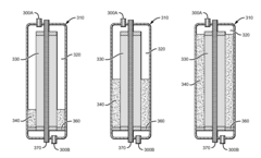
[0020]The inventive subject matter provides apparatus, systems and methods in which one can efficiently perform pressurized filtration of fluids. Such filtration can be performed using a filtration device that includes a filter assembly with a semipermeable membrane that permits selective transport of fluid components across the membrane under a pressure gradient, and a housing that encloses such a filter assembly. As noted above, the rate of transport across such membrane filters is a function of factors such as the available membrane surface area and the magnit...


PUM

PropertyMeasurementUnit
thickaaaaaaaaaa
wall thicknessaaaaaaaaaa
thicknessaaaaaaaaaa

Abstract

The present inventive concept relates to devices and methods for pressure filtration utilizing spiral wound membranes, in which the volume between the filter membrane and the filter housing is partially or essentially completely filled with an impermeable material. The resulting device permits rapid filtration rates with improved pressure resistance and reduced contamination and microbial growth within the filtration device.

Description

FIELD OF THE INVENTION[0001]The field of the invention is pressurized ultrafiltration and, more particularly, ultrafiltration modules for use in various reverse osmosis applications, and a method of constructing same.BACKGROUND[0002]Ultrafiltration is a separation technology in which a pressure gradient is generated across a semipermeable membrane. Suspended solids, high molecular weight molecules, salts, and other components of the feed stream applied to the ultrafiltration device that cannot pass through the semipermeable membrane are retained in the feed stream, whereas components of the feed stream that can pass through the semipermeable membrane are collected as a permeate. Useful products from the process can be the permeate, the concentrated feed stream, or both.[0003]The selectivity of the semipermeable membrane is due, at least in part, to the dimensions of pores or channels that transect the membrane's thickness. Semipermeable membranes are available in a variety of materi...

Claims


Application Information

Patent Timeline
Patent Type & Authority Applications(United States)
IPC IPC(8): B01D63/10
CPCB01D63/10B01D63/107B01D2313/041
Inventor CHANCELLOR, DENNIS
Owner CHANCELLOR DENNIS H