Method for manufacturing a magnetic separation for a solenoid valve

a solenoid valve and magnetic separation technology, which is applied in the direction of valve operating means/release devices, machines/engines, etc., can solve the problems of high cost of joining parts, affecting the dynamics of force build-up and decay, and reducing the magnetic force obtainable, etc., to achieve high-efficiency magnetic separation and inexpensible production

Inactive Publication Date: 2014-11-27
ROBERT BOSCH GMBH
View PDF9 Cites 2 Cited by
  • Summary
  • Abstract
  • Description
  • Claims
  • Application Information

AI Technical Summary

Benefits of technology

[0006]An object of the present invention is to provide an inexpensively producible, high-efficiency magnetic separation for a magnetic circuit for actuating valves.
[0007]In comparison with the related art, the solenoid valve of the present invention and the method of the present invention for manufacturing a solenoid valve, according to the alternative independent claims, have the advantage that the low wall thickness of the sleeve in the thin-walled region achieves an optimum magnetic separation effect (without a complete mechanical “magnetic separation”), since the remaining cross-sectional area is already in the state of magnetic saturation in response to comparatively low magnetic flux. It is also advantageous that the wall thickness may be selected to be comparatively low, since the wall thickness assumes only the function of sealing and does not have to transmit the circumferential and axial forces resulting from the internal pressure. It is further advantageous that a reliable seal is ensured, since the sleeve is made of a continuous component part. Furthermore, it is advantageous that the solenoid valve of the present invention may also be used in applications having a very high internal pressure, since the reinforcing element has a high tensile strength and a high stiffness.
[0008]Moreover, it is advantageous that the solenoid valve of the present invention may be produced comparatively inexpensively. Since the sleeve is in one piece, no expensive handling, joining and aligning operations are necessary. In addition, the need for an imperviousness test is eliminated. It is also advantageous that the geometry of the magnetic separation is clearly defined and strictly delimited. Furthermore, it is advantageous that both welding of different parts of the sleeve and welding of the sleeve to a reinforcing element are not necessary, since the sleeve is in one piece. By eliminating the need for welding, thermal distortion may be avoided, which means that reworking may be dispensed with. The sleeve may be made of a ferromagnetic material, and the reinforcing element is made of an austenitic (steel) material.

Problems solved by technology

However, a sleeve that is magnetically soft throughout has the disadvantage that a portion of the magnetic flux does not penetrate the inner pole and armature of the magnetic circuit and the air gap situated between them, as desired, but remains in the sleeve.
Thus, the magnetic circuit is short-circuited by the sleeve, which causes a marked reduction in the magnetic force obtainable and affects the dynamics of the force build-up and decay.
In the case of a multipart sleeve, the high expenditure of joining the parts, the test for imperviousness, and the necessary reworking, e.g., due to thermal distortion, are to be regarded as unfavorable.
The method of local thermal influencing of the magnetic properties does not allow complete neutralization of the magnetizability of the material, produces an unsharp separation due to the zones of heat influx, and may also cause distortion of the sleeve.
In addition, the configuration approach of a reduction in wall thickness, which is the simplest from a standpoint of production engineering, is a rather poor compromise from a functional point of view, since for reasons of strength, a relatively high residual wall thickness is necessary.
This limits the effectiveness of the magnetic separation, and consequently, the performance of the solenoid valve.

Method used


Image

  • Method for manufacturing a magnetic separation for a solenoid valve
  • Method for manufacturing a magnetic separation for a solenoid valve
  • Method for manufacturing a magnetic separation for a solenoid valve

Examples


first embodiment

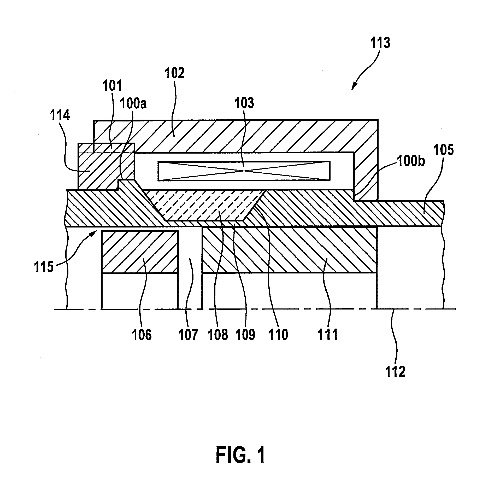
[0028]FIG. 2 schematically shows a portion of solenoid valve 113 variant of the present invention also illustrated in FIG. 1; thin-walled region 110 forming an annular groove in sleeve 105. This means that in the axial direction, sleeve 105 has, for example, a constant inner diameter, and also in the axial direction, the sleeve has a lower outer diameter in the area of thin-walled region 110 than in front of and after thin-walled region 110, in the axial direction; it being provided, in particular, that the change in (outer) diameter occur gradually via a beveled region 110′.

[0029]However, as an alternative to that, according to a further specific embodiment (also not shown), the present invention may also provide that the change in (outer) diameter occur nearly without a transition (that is, a step change in diameter occurs).

second embodiment

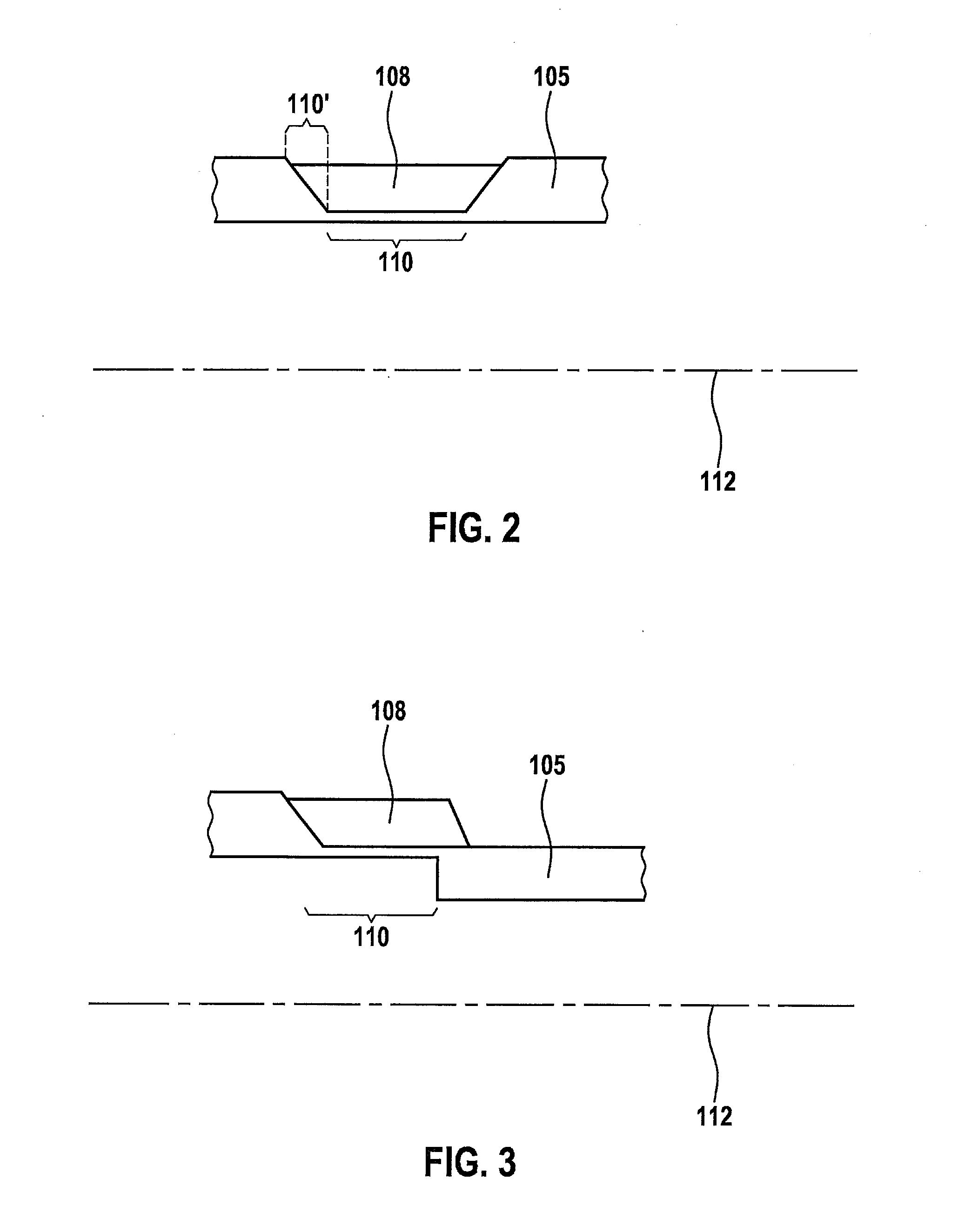
[0030]FIG. 3 schematically shows a portion of a solenoid valve 113 variant of the present invention; thin-walled region 110 not forming an annular groove in sleeve 105, but being formed in such a manner, that a change in the inner and outer diameter of sleeve 105 is provided in the area of the ends of thin-walled region 110. This means that the inner diameter of sleeve 105 changes in the axial direction at one end of thin-walled region 110, and that the outer diameter of sleeve 105 changes in the axial direction at the opposite end of thin-walled region 110; in the case of this change in diameter as well, either a gradual change in diameter being able to be produced (along the axial direction), or else a step change in diameter. In the illustrated example of FIG. 3, a gradual diameter change is exemplarily shown in the case of the change of the outer diameter (in the left part of the figure), and a step change in diameter is exemplarily shown in the case of the change of the inner ...


PUM

PropertyMeasurementUnit
melting pointaaaaaaaaaa
wall thicknessaaaaaaaaaa

Abstract

A method for manufacturing a solenoid valve or a fuel injector, including a sleeve, a valve needle situated inside the sleeve in a radial direction and guided so as to slide, a solenoid coil situated outside of the sleeve in a radial direction, a magnetic core situated inside the sleeve in a radial direction, and a magnet armature situated inside the sleeve in a radial direction, axially opposite to the magnetic core; the magnet armature being situated on the valve needle, the sleeve having a low wall thickness in a thin-walled region situated between the magnet armature and the solenoid coil, the thin-walled region strengthened by a reinforcing element for absorbing radial forces; and a method step, during which, the reinforcing element is deposited onto the sleeve, in the thin-walled region, in a radial direction, outside of the sleeve, using a molten bath or cold gas spraying method.

Description

FIELD[0001]The present invention is directed to a method for manufacturing a solenoid valve.BACKGROUND INFORMATION[0002]In the case of electromagnetically operable solenoid actuators for operating solenoid valves, in particular, of injection valves, it is often useful to position a magnetic coil used for generating a magnetic field, outside of a region through which a fluid, in particular, fuel, flows. This facilitates assembly and prevents, e.g., damage to the lacquer layer of the coil wire by the action of fuel. In order to produce such a dry coil arrangement, metallic sleeves are used, which seal the fuel-filled valve interior in the direction of the coil. In order to withstand the fuel pressure in the interior of the sleeve (e.g., pressures of greater than 200 bar internal pressure), the sleeve must have a sufficient wall thickness.[0003]At the same time, it must be ensured that the magnetic flux may reach the magnetic circuit components situated in the interior (armature, i.e.,...

Claims


Application Information

Patent Timeline
Patent Type & Authority Applications(United States)
IPC IPC(8): F16K31/06H01F41/00
CPCH01F41/00F16K31/0675H01F7/081H01F41/0246H01F2007/085F02M2200/9069F02M2200/80F02M2200/08F02M2200/9038Y10T29/4902
Inventor GRANER, JUERGENMAIER, MARTINHAUTMANN, NIKOLAUSDIEKMANN, RALF
Owner ROBERT BOSCH GMBH
Why Eureka
Try Eureka