Switched-capacitor isolated LED driver

a technology of led driver and capacitor, applied in the direction of electric variable regulation, process and machine control, instruments, etc., can solve the problems of significant circuit space occupation, significant thermal conductivity reduction, heat sink becoming a safety hazard, etc., and achieve the effect of enabling simple heat sinking of led devices

Active Publication Date: 2014-11-27
RGT UNIV OF CALIFORNIA
View PDF6 Cites 66 Cited by
  • Summary
  • Abstract
  • Description
  • Claims
  • Application Information

AI Technical Summary

Benefits of technology

[0015]A switched-capacitor galvanically isolated LED driver circuit is described. The disclosed circuit provides an electrical conversion interface, and means for LED lamp current regulation, when operating from an intermediate voltage bus (e.g., rectified 110 VAC line voltage). The disclosed invention can provide this galvanic isolation at different locations in the system. In one form of isolation, LED devices are in close thermal contact with the heat sink/heat spreader with the LED lamp

Problems solved by technology

These LED drive circuits may also require bulk electrolytic capacitance, that is usually considered the weak link in terms of lifetime and reliability of the devices, while also taking up significant circuit space.
Although, in this configuration, the heat sink becomes a safety hazard because many existing fixtures, such as standard Edison sockets,

Method used


Image

  • Switched-capacitor isolated LED driver
  • Switched-capacitor isolated LED driver
  • Switched-capacitor isolated LED driver

Examples


Embodiment Construction

[0035]The present invention is a switched-capacitor driver circuit which provides isolation from the main supply and is particularly well-suited for use in driving LEDs lamps. One of the objects of the invention is providing a substantial circuit cost reduction by eliminating large transformers, while increasing device lifespan through reduction or elimination of electrolytic capacitors. The following outlines a number of embodiments of these switched-capacitor LED driver circuits which are isolated from supply mains.

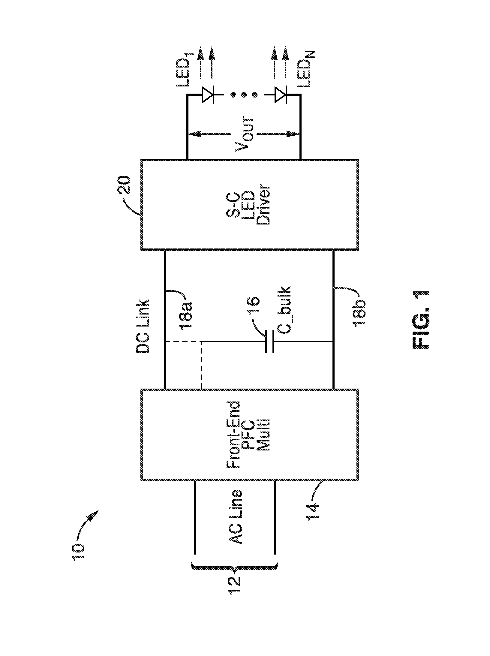
[0036]FIG. 1 illustrates an example embodiment 10 of a switched-capacitor driver receiving an input signal 12 (e.g., AC line voltage) into a power factor correction (PFC) rectifier 14, a DC bus or link shown with bulk capacitor 16 between DC lines 18a, 18b, and connecting to an LED driver section 20 with VOUT to a series of LEDs, shown as LED1 through LEDN. The DC bus or link in this example, has a voltage in the range of 170-200 V, for a 110 Vrms AC line. The figure in...


PUM


Abstract

A switched-capacitor voltage converter which is particularly well-suited for receiving a line voltage from which to drive current through a series of light emitting diodes (LEDs). Input voltage is rectified in a multi-level rectifier network having switched capacitors in an ascending-bank configuration for passing voltages in uniform steps between zero volts up to full received voltage VDC. A regulator section, operating on VDC, comprises switched-capacitor stages of H-bridge switching and flying capacitors. A current controlled oscillator drives the states of the switched-capacitor stages and changes its frequency to maintain a constant current to the load. Embodiments are described for isolating the load from the mains, utilizing an LC tank circuit or a multi-primary-winding transformer.

Description

CROSS-REFERENCE TO RELATED APPLICATIONS[0001]This application is a 35 U.S.C. §111(a) continuation of PCT international application number PCT / US2012 / 068610 filed on Dec. 7, 2012, incorporated herein by reference in its entirety, which claims priority to, and the benefit of, U.S. provisional patent application No. 61 / 568,731 filed on Dec. 9, 2011, incorporated herein by reference in its entirety. Priority is claimed to each of the foregoing applications.[0002]The above-referenced PCT international application was published as PCT International Publication No. WO 2013 / 086445 on Jun. 13, 2013, which publication is incorporated herein by reference in its entirety.STATEMENT REGARDING FEDERALLY SPONSORED RESEARCH OR DEVELOPMENT[0003]This invention was made with government support under ADEPT DE-AR0000114 awarded by the U.S. Department of Energy (DOE) through the Advanced Research Projects Agency-Energy (ARPA-E). The government has certain rights in the invention.INCORPORATION-BY-REFERENCE...

Claims


Application Information

Patent Timeline
IPC IPC(8): H05B33/08H02M1/42H02M3/335H05B44/00
CPCH05B33/0815H02M1/4208H02M3/33507Y02B20/30H05B45/3725H05B45/382
Inventor SANDERS, SETH R.KLINE, MITCHELL
Owner RGT UNIV OF CALIFORNIA
Why Eureka
Try Eureka