Fault Detection Device For Inverter System

a technology of fault detection and inverter, which is applied in the direction of power supply testing, dynamo-electric converter control, instruments, etc., can solve the problem of not being able to detect faults in inverter circuits, and achieve the effects of simple circuit, low cost manufacturing, and easy manufacturing

Active Publication Date: 2014-11-27
SANDEN CORP
View PDF8 Cites 15 Cited by
  • Summary
  • Abstract
  • Description
  • Claims
  • Application Information

AI Technical Summary

Benefits of technology

[0012]According to the invention relating to claim 1, it is possible to apply the predetermined first test voltage to the current measuring unit when the driving start signal of the inverter circuit is input, to determine whether the current measuring unit has failed or not based on the applied first test voltage. Then, it is possible to apply the predetermined second test voltage to the inverter circuit and the motor, to determine whether the inverter circuit and the coil of the motor have failed or not based on the applied second test voltage. Accordingly, it is possible to detect the fault in the current measuring unit before the start of driving of the inverter system. Furthermore, it is possible to detect the fault in the inverter circuit and the fault in the coil of the motor. In this case, since the number of the current measuring unit is one, the circuit can be simplified and can be easily manufactured. Furthermore, since the number of components is small, it is possible to manufacture the circuit at low cost. In particular, when a shunt resistor is used in the current measuring unit, only one expensive amplification circuit for measuring the current based on a very small voltage drop in the shunt resistor is required, and thus, it is possible to manufacture the circuit at low cost.
[0013]According to the invention relating to claim 2, even when the first test voltage amplified by the amplification circuit provided in the current measuring unit is greater than the upper limit value of the voltage range that is determined in advance or even when the amplified voltage is less than the lower limit value thereof, the control unit can perform the determination as to whether the current measuring unit has failed or not. Accordingly, it is possible to reliably detect the fault in the current measuring unit.
[0014]According to the invention relating to claim 3, even when the second test voltage amplified by the amplification circuit provided in the current measuring unit is greater than the upper limit value of the voltage range that is determined in advance or even when the amplified voltage is less than the lower limit value thereof, the control unit can perform the determination as to whether the inverter circuit and the coil of the motor have failed or not. Accordingly, it is possible to reliably detect the fault in the inverter circuit and the coil of the motor.
[0015]According to the invention relating to claim 4, when the predetermined time elapses from the start of application of the second test voltage, the control unit can determine whether the inverter circuit and the coil of the motor have failed or not. Accordingly, it is possible to accurately determine the fault in the inverter circuit and the coil of the motor.

Problems solved by technology

In this case, when detection of fault in the inverter circuit is performed, and if the current measuring unit has failed, it is not possible to measure the current of the inverter circuit, and consequently, it is not possible to detect the fault in the inverter circuit.

Method used


Image

  • Fault Detection Device For Inverter System
  • Fault Detection Device For Inverter System
  • Fault Detection Device For Inverter System

Examples


Embodiment Construction

[0034]Embodiments of the invention will now be described with reference to the accompanying drawings.

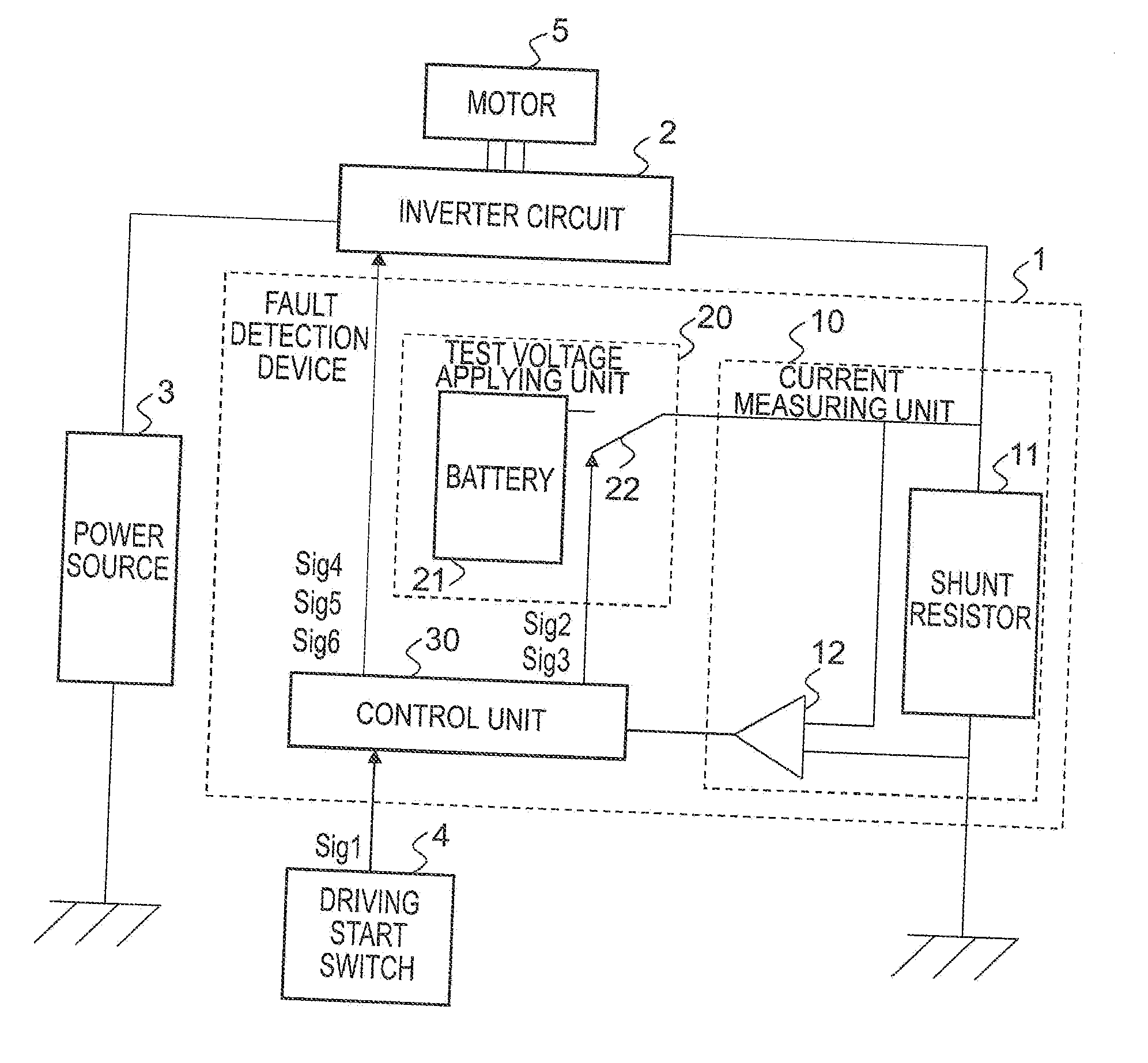
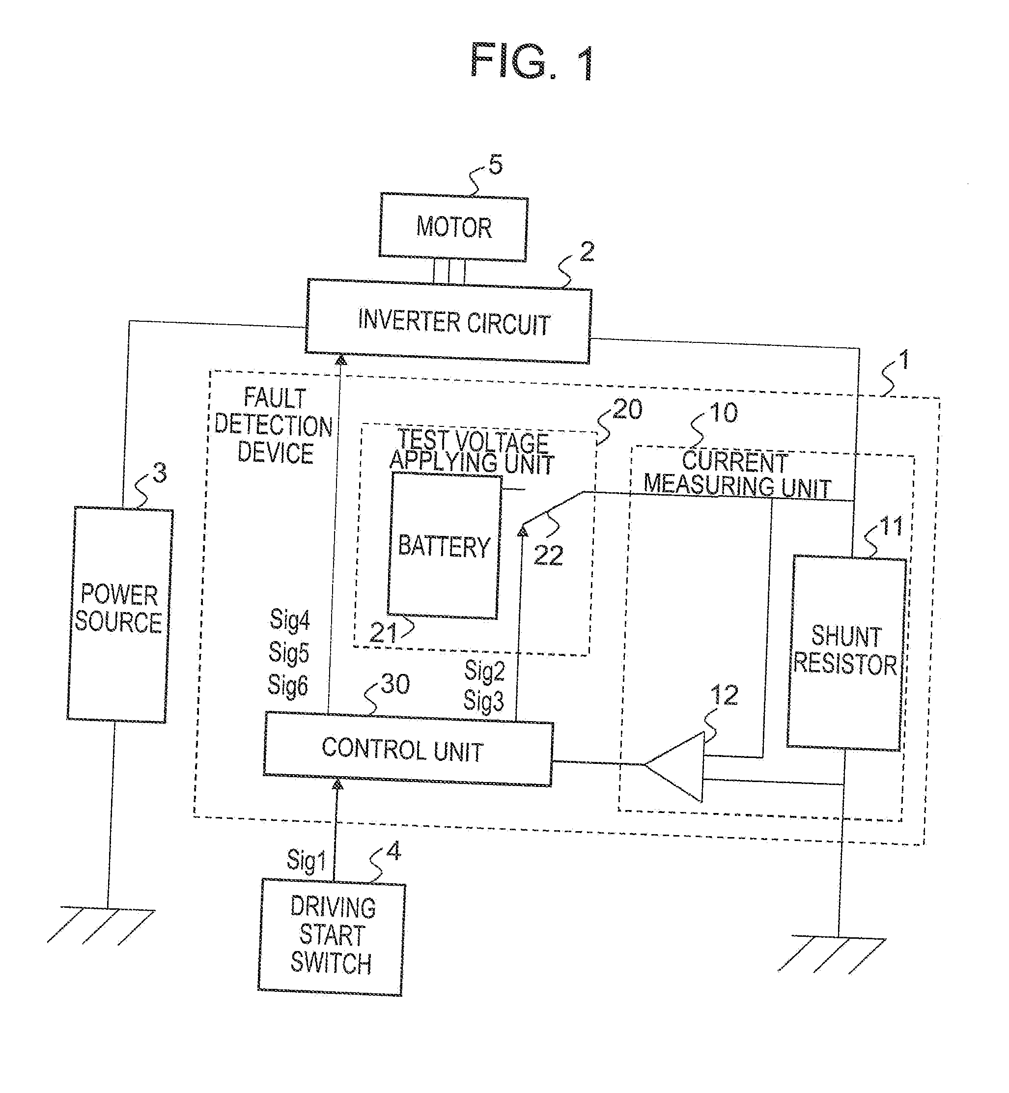
[0035]FIG. 1 is a block diagram illustrating a fault detection device for an inverter system according to an embodiment of the invention. A circuit illustrated in the block diagram of FIG. 1 represents a use state where a fault detection device 1 for an inverter system according an embodiment of the invention (hereinafter, referred to as a “fault detection device”) is connected to an inverter circuit 2 that is a fault detection target, in which the inverter circuit 2, a power source 3 and a driving start switch 4 are connected to the fault detection device 1 and a motor 5 is connected to the inverter circuit 2. The inverter circuit 2 is a circuit that is used for controlling the motor 5 or the like and converts DC power supplied from the power source 3 into AC power. The power source 3 supplies the DC power to the inverter circuit 2. The driving start switch 4 is a switch for startin...


PUM


Abstract

To provide a fault detection device for an inverter system, that detects a fault in the inverter system including an inverter circuit 2 that converts DC power into AC power and a motor 5 driven thereby. When a driving start signal Sig1 of the inverter circuit 2 is input, a test voltage applying unit 20 applies a predetermined first test voltage to a current measuring unit 10 that measures current flowing in the inverter circuit 2, and it is determined whether the current measuring unit 10 has failed, based on the first test voltage. A control unit 30 applies a predetermined second test voltage to the inverter circuit 2 and the motor 5, and it is determined whether the inverter circuit 2 and a motor coil have failed, based on the second test voltage.

Description

TECHNICAL FIELD[0001]The present invention relates to a fault detection device that detects a fault in an inverter system that includes an inverter circuit and a motor driven by the inverter circuit, and more particularly, relates to a fault detection device for an inverter system capable of detecting a fault in a current measuring unit that measures current flowing in an inverter circuit before the start of driving of the inverter system, determining thereafter a fault in the inverter circuit and a motor coil, and being easily manufactured at low cost.BACKGROUND ART[0002]A conventional fault detection device for an inverter circuit includes: a current measuring unit that measures current of an inverter circuit that drives a motor; an overcurrent determination circuit that determines whether the measured current is overcurrent based on an output signal of the current measuring unit; and an inverter-output control circuit that controls an output of an inverter driving circuit that dr...

Claims


Application Information

Patent Timeline
Patent Type & Authority Applications(United States)
IPC IPC(8): G01R31/02G01R31/50H02M1/00
CPCG01R31/02H02P27/06H02M1/32H02M7/5387G01R31/34G01R31/42H02P29/0241G01R31/50H01L2221/00H02P1/00H02P29/024
Inventor HIRONO, DAISUKE
Owner SANDEN CORP
Why Eureka
Try Eureka