3D Light Field Displays and Methods with Improved Viewing Angle, Depth and Resolution

a technology of light field and display, applied in the field of image and video displays, can solve the problems of its own limitations, limited quality, and designer being faced with having to make the combination of the other two parameters wors

Inactive Publication Date: 2014-11-27
OSTENDO TECH INC
View PDF17 Cites 46 Cited by
  • Summary
  • Abstract
  • Description
  • Claims
  • Application Information

AI Technical Summary

Problems solved by technology

Even though integral imaging technology is the preferred method of generating full parallax 3D images, it has its own limitations.
For an integral imaging display this quality is limited by the pixel pitch of the spatial modulator and to improve any one of these parameters, a designer is usually faced with having to make the combination of the other two parameters worse.
There have been attempts at improving the viewing angle of integral imaging displays without worsening the other two parameters, but these attempts were impractical to manufacture, offered little improvement, or degraded an aspect of a display not explained in the characteristic equation so much that the resulting image was unusable.
The main problem associated with the mask based methods is that at any time only half of the lenses in the lens array have access to all the pixels in the display device.
This means that either the pixels in the display device have to be shared using time multiplexing, increasing the complexity and the processing requirements of the device, or the number of pixels has to be increased by adding another display device, increasing the space occupied by the display system.
There are four problems associated with this method.
The first problem is the manufacturability of micro convex mirror arrays.
As of now there is no practical way to manufacture micro convex mirror arrays therefore the method had to use the reflection from the convex lens array.
Because the reflectance of the convex lenses is only 4% the brightness of the image suffers.
The third problem is the supporting of only the virtual mode integral images limits the usability and attractiveness of the display.
Finally the fourth problem is the space that is taken by the system.
As with any front projection system the projectors have to be located behind the observers to project the image on the screen, limiting th...

Method used


Image

  • 3D Light Field Displays and Methods with Improved Viewing Angle, Depth and Resolution
  • 3D Light Field Displays and Methods with Improved Viewing Angle, Depth and Resolution
  • 3D Light Field Displays and Methods with Improved Viewing Angle, Depth and Resolution

Examples


Embodiment Construction

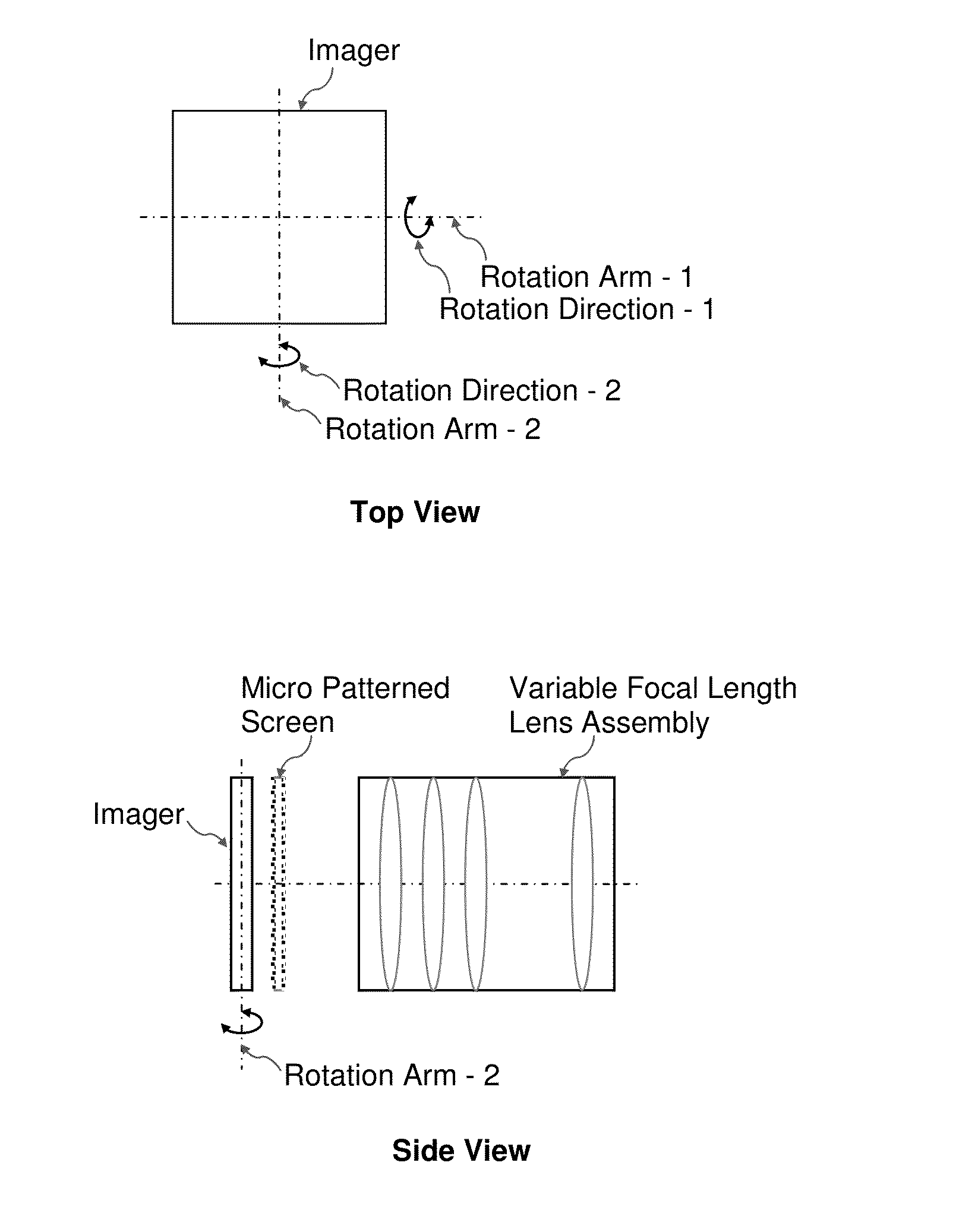
[0112]The invention described herein details an easy to manufacture, high brightness, no color break up, wide viewing angle integral imaging system that does not sacrifice image resolution or image depth.

[0113]With the availability of high brightness, vertical stacking, small pixel pitch displays, Ref. [10], [12] and [13], a full parallax integral imaging display with a wide viewing angle and improved picture quality is feasible. This invention presents a method of improving the viewing angle of an integral imaging display without degrading the image resolution or the image depth. The invention eliminates the color distortions found in other integral imaging displays and achieves very high brightness in a very small volume.

[0114]These new types of emissive solid state displays have 10 μm or smaller pixel pitch, high dynamic range, and fast modulation speed, Refs [12], [13]. These types of displays, which can be driven by multi-core matched instruction set processors Ref [14] that ar...


PUM


Abstract

3D light field display methods and apparatus with improved viewing angle, depth and resolution are introduced. The methods can be used to create a high quality 3D light field display of any size from smaller than a postage stamp to larger than a three story building.

Description

CROSS-REFERENCE TO RELATED APPLICATIONS[0001]This application is a continuation of International Application No. PCT / US2014 / 029623 Filed Mar. 14, 2014 which claims the benefit of U.S. Provisional Patent Application No. 61 / 800,818 filed Mar. 15, 2013.BACKGROUND OF THE INVENTION[0002]1. Field of the Invention[0003]This invention relates generally to image and video displays, more particularly to 3D light field imaging systems and the construction methods of 3D light field imaging systems with large viewing angle, high frequency and extended depth. The term “light field” describes the transmission and modulation of the light including, direction, amplitude, frequency and phase, and therefore encapsulates imaging systems that utilize techniques such as holography, integral imaging, stereoscopy, multi-view imaging, Free-viewpoint TV (FTV) and the like. The invention described herein details an easy to manufacture, high brightness, no color break up, wide viewing angle 3D light field imag...

Claims


Application Information

Patent Timeline
IPC IPC(8): G06T15/50H04N13/307
CPCG06T15/50H04N13/307G02B30/10
Inventor ALPASLAN, ZAHIR Y.EL-GHOROURY, HUSSEIN S.
Owner OSTENDO TECH INC
Why Eureka
Try Eureka