Collision ion generator and separator

a technology of collision ion and generator, which is applied in the direction of particle separator tube details, separation processes, instruments, etc., can solve the problems of low sensitivity of this technique, chemical derivatization fails in case of larger molecules, and is not feasible for evaporation of these compounds prior to electrical charging

Active Publication Date: 2014-12-04
MEDIMASS +1
View PDF1 Cites 43 Cited by
  • Summary
  • Abstract
  • Description
  • Claims
  • Application Information

AI Technical Summary

Benefits of technology

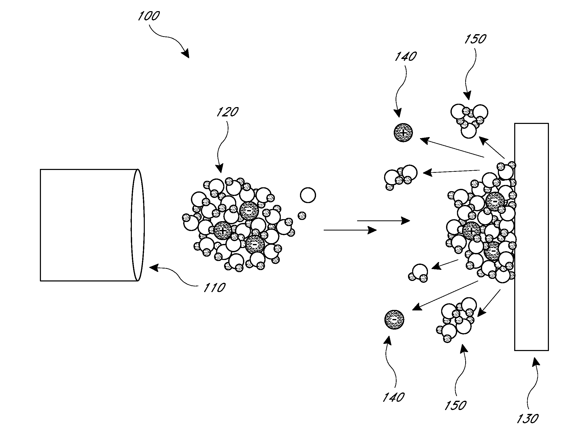
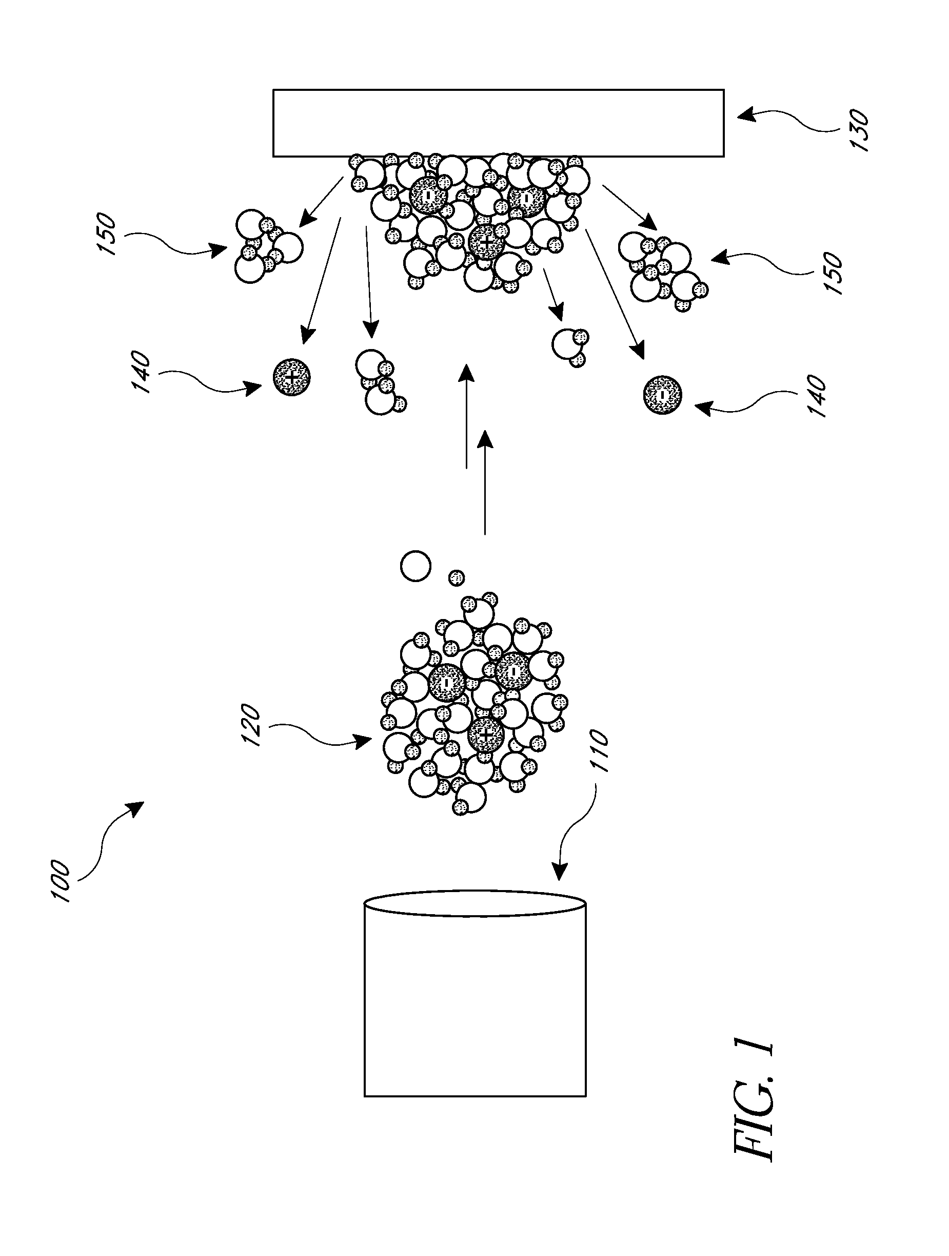
[0013]In some embodiments, a method for generating gaseous molecular ions for analysis by a mass spectrometer or ion mobility spectrometer includes accelerating a sample toward a solid surface, colliding the sample with the solid surface, and collecting the resulting gaseous molecular ions and directing them to an analyzer unit. The sample includes one of an aerosol sample and a liquid sample which further includes one or more of molecular particle clusters, solid particles and charged particles. The collision is intended to disintegrate the one or more molecular particle clusters, thereby forming one or more gaseous molecular ions, neutral molecules, and smaller-sized molecular particle clusters.
[0014]In some embodiments, a system for generating gaseous molecular ions for analysis by a mass spectrometer or ion mobility spectrometer includes a tubular conduit, a collision element, and a skimmer electrode. The tubular conduit is configured to accelerate a sample therethrough. The sample accelerated within the system includes one of an aerosol sample and a liquid sample and has one or more of molecular particle clusters, solid particles and charged particles. The collision element is spaced apart from an opening of the tubular conduit and is generally aligned with an axis of the tubular conduit. The collision element has a surface upon which the sample collides, disintegrating the one or more molecular particle clusters to form one or more of gaseous molecular ions, neutral molecules and smaller-sized molecular particle clusters. The skimmer electrode is configured to collect the gaseous molecular ions. The skimmer electrode has an opening generally aligned with the tubular conduit opening, such that the collision element is interposed between the tubular conduit opening and the skimmer electrode.
[0015]In some embodiments, a system for generating gaseous molecular ions for analysis by a mass spectrometer or ion mobility spectrometer includes a tubular conduit, a collision element, and an ion funnel guide assembly. The tubular conduit is configured to accelerate a sample therethrough. The sample accelerated through tubular conduit includes one of an aerosol sample and a liquid sample and has one or more of molecular particle clusters, solid particles and charged particles. The collision element is spaced apart from an opening of the tubular conduit and is generally aligned with an axis of the tubular conduit. The collision element has a generally spherical surface on which the sample collides. The collision between the sample and the generally spherical collision element disintegrates the one or more molecular particle clusters to form one or more gaseous molecular ions, neutral molecules and smaller-sized molecular particle clusters. The ion funnel guide assembly is generally aligned with the tubular conduit opening and is driven by a bipolar radiofrequency alternating current. The collision element is disposed in the ion funnel. The ion funnel guide assembly is configured to separate the gaseous molecular ions from the neutral molecules and smaller sized molecular particle clusters, and to direct the gaseous molecular ions to an analyzer.
[0016]In some embodiments, a system for generating gaseous molecular ions for analysis by a mass spectrometer and / or ion mobility spectrometer includes a tubular conduit, a skimmer electrode, and an analyzer unit. The tubular conduit is configured to accelerate a sample therethrough. The sample accelerated through the tubular conduit includes one of an aerosol sample and a liquid sample and has one or more of molecular particle clusters, solid particles and charged particles. The skimmer electrode is spaced apart from and generally aligned with an opening of the tubular conduit. The skimmer electrode has a tubular section with a surface upon which the sample particles collide to generate gaseous molecular ions. The analyzer unit which receives the gaseous molecular ions from the skimmer electrode is configured to analyze the gaseous molecular ions to provide information on the chemical composition of the sample.

Problems solved by technology

Since certain molecular constituents are non-volatile, the evaporation of these compounds is not feasible prior to electrical charging.
However, chemical derivatization also fails in case of larger molecules, representatively including oligosaccharides, peptides, proteins, and nucleic acids.
The low sensitivity of this technique combined with its incompatibility with chromatographic separation hinders its general applicability to the quantitative determination of biomolecules in biological matrices.
The poor sensitivity from which desorption ionization methods suffer is generally associated with the fact that most of the material is desorbed in the form of large molecular clusters with low or no electric charging.
While theoretically spray ionization methods are able to provide nearly 100% ionization efficiency, such a high value is generally not reached because of practical implementation issues.
Nanoelectrospray, or nanospray, methods give very high ionization efficiency but are limited to extremely low flow rates; such methods can only give high ionization efficiency for flow rates in the low nanoliter per minute range.
Since practical liquid chromatographic separations involve higher liquid flow rates (e.g., including high microliters per minute to low milliliters per minute), nanospray is not the usual method of choice for liquid chromatographic-mass spectrometric systems.
Similarly to desorption ionization methods, spray ionization sources also produce considerable amounts of charged and neutral clusters which decreases ionization efficiency and can tend to contaminate mass spectrometric atmospheric interfaces.
Such a combination of skimmer electrode and radio-frequency alternating potential driven multi-pole ion guides can allow up to 30% ion transmission efficiency; however, it does not solve or manage the problem of contamination by larger molecular clusters.

Method used


Image

  • Collision ion generator and separator
  • Collision ion generator and separator
  • Collision ion generator and separator

Examples


example 1

Ionization of Surgical Aerosol

[0070]The system illustrated in FIG. 5 was used in this example. Surgical electrocautery was done using a handpiece containing a monopolar cutting electrode. The cutting blade was embedded in an open 3.175 mm diameter stainless steel tube which was connected to a flexible polytetrafluoroethylene (PTFE) tube 2 m long and 3.175 mm in diameter. The PTFE tube was used to transport the aerosol containing gaseous ions from the surgical site to the mass spectrometer by means of a Venturi gas jet pump. The Venturi pump was operated at a flow rate of 20 L / min. The pump exhaust was placed orthogonally to the atmospheric inlet of the mass spectrometer.

[0071]Porcine hepatic tissue was sampled using the electrocautery system as just described. The surgical smoke was lead into the modified atmospheric interface of an LCQ Advantage Plus (Thermo Finnigan, San Jose, Calif.) mass spectrometer and the spectra produced analyzed.

[0072]The sample does not contain few if any ...


PUM

PropertyMeasurementUnit
temperaturesaaaaaaaaaa
temperatureaaaaaaaaaa
diameteraaaaaaaaaa

Abstract

According to some embodiments, systems and methods for surface impact ionization of liquid phase and aerosol samples are provided. The method includes accelerating a liquid or aerosol sample, colliding the sample with a solid collision surface thereby disintegrating the sample into both molecular ionic species (e.g., gaseous molecular ions) and molecular neutral species (e.g., gaseous sample), and transporting the disintegrated sample to an ion analyzer. Some embodiments of the method further comprise discarding the molecular neutral species. Such embodiments transport substantially only the molecular ionic species to the ion analyzer.

Description

BACKGROUND OF THE INVENTION[0001]1. Field[0002]The present invention relates to devices, systems and methods for quantifying, analyzing and / or identifying chemical species. More specifically, the present invention relates to devices, systems and methods for the conversion of certain molecular components of aerosols and liquid phase samples to gaseous molecular ions through a surface impact phenomenon which disintegrates aerosol particles or liquid jets into smaller particles including gas-phase molecular ions.[0003]2. Description of the Related Art[0004]Mass spectrometry is generally used for the investigation of the molecular composition of samples of arbitrary nature. In traditional mass spectrometric analysis procedures, the molecular constituents of samples are transferred to their gaseous phase and the individual molecules are electrically charged to yield gas-phase ions which can then be subjected to mass analysis, such as separation and selective detection of the ions based o...

Claims


Application Information

Patent Timeline
Patent Type & Authority Applications(United States)
IPC IPC(8): H01J49/00H01J49/04H01J49/14G01N27/62G01N27/622
CPCH01J49/0031H01J49/0445H01J49/14H01J49/0454H01J49/16H01J49/142
Inventor SZALAY, DANIELGODORHAZY, LAJOSTAKATS, ZOLTAN
Owner MEDIMASS
Why Eureka
Try Eureka