Power reserve apparatus, power system, and electric vehicle

a technology of power reserve apparatus and power system, which is applied in the direction of battery/fuel cell control arrangement, electric devices, etc., can solve the problems of not being able to fully utilize the capacity of these battery cells, the size of circuits and circuit boards can be reduced, and the time taken to complete balance adjustment becomes longer. , to prevent the overall voltage from decreasing, the effect of reducing the size of the circuit and the circuit board

Active Publication Date: 2014-12-04
MURATA MFG CO LTD
View PDF6 Cites 63 Cited by
  • Summary
  • Abstract
  • Description
  • Claims
  • Application Information

AI Technical Summary

Benefits of technology

[0021]In the present disclosure, since inter-cell voltage adjustment (referred to as inter-cell balance adjustment or cell balance) is performed using passive balance control, the sizes of circuits and circuit boards can be reduced without requiring inductor elements. On the other hand, since inter-module voltage adjustment (referred to as inter-module balance adjustment or inter-module balance) is performed using active balance control, it is possible to prevent the overall voltage from decreasing. Furthermore, when the inter-module balance adjustment is performed, a difference in voltage larger than in the case of the inter-cell balance adjustment needs to be eliminated, and therefore when the inter-module balance adjustment is performed using the passive balance adjustment, the time taken to complete the balance adjustment becomes longer. Therefore, as in the present disclosure, by combining the inter-cell balance adjustment and the inter-module balance adjustment, the time taken to complete the balance adjustment is reduced.

Problems solved by technology

In the case of using a plurality of battery cells, even when one of the plurality of battery cells has reached a lower limit of working voltage during discharging, other battery cells may not have still reached the lower limit of the working voltage due to differences in self-discharge between the battery cells or the like.
When the battery cells are charged again in such a state, some battery cells cannot be fully charged, thereby posing a problem in that the capacity of these battery cells cannot be fully utilized.
Because a power reserve apparatus includes an extremely large number of battery cells in the case of an on-vehicle battery, a domestic power storage apparatus, or the like, there has been a problem in that it takes a long time to equalize the voltages of all the battery cells.
However, when voltage is equalized by resistors, the voltages of the battery cells and the power storage modules undesirably decrease as a whole, and therefore a large number of times of charging and a large number of times of discharging for adjusting the voltages need to be repeated in order to set these voltages to a target value.
Therefore, it takes a long time to complete the voltage adjustment of the power reserve apparatus.
Especially when there is cyclic deterioration of a positive / negative active material, variation in the temperature condition, or a decrease in the amount of power in a battery cell according to an increase in internal resistance, the balance between the amounts of power in the battery cells is lost to a great extent and it takes a longer time to complete the voltage adjustment.
Furthermore, the variation of the battery cells cannot be adjusted between the modules, and it is difficult to keep the balance.
In a circuit configuration that equalizes voltage by moving electric charge using coils, voltage can be equalized in a relatively short period of time, but the arrangement of the coils and the switching elements and the control of the switching elements are complex, and a large number of coils need to be arranged in such a way as to enable smooth transmission of power.

Method used


Image

  • Power reserve apparatus, power system, and electric vehicle
  • Power reserve apparatus, power system, and electric vehicle
  • Power reserve apparatus, power system, and electric vehicle

Examples


Embodiment Construction

[0043]Embodiments that will be described hereinafter are preferable specific examples of the present disclosure and various technologically preferable limitations are provided therefor, but the scope of the present disclosure is not limited to these embodiments in the following description unless description for limiting the present disclosure is specifically included.

“Power Reserve Apparatus”

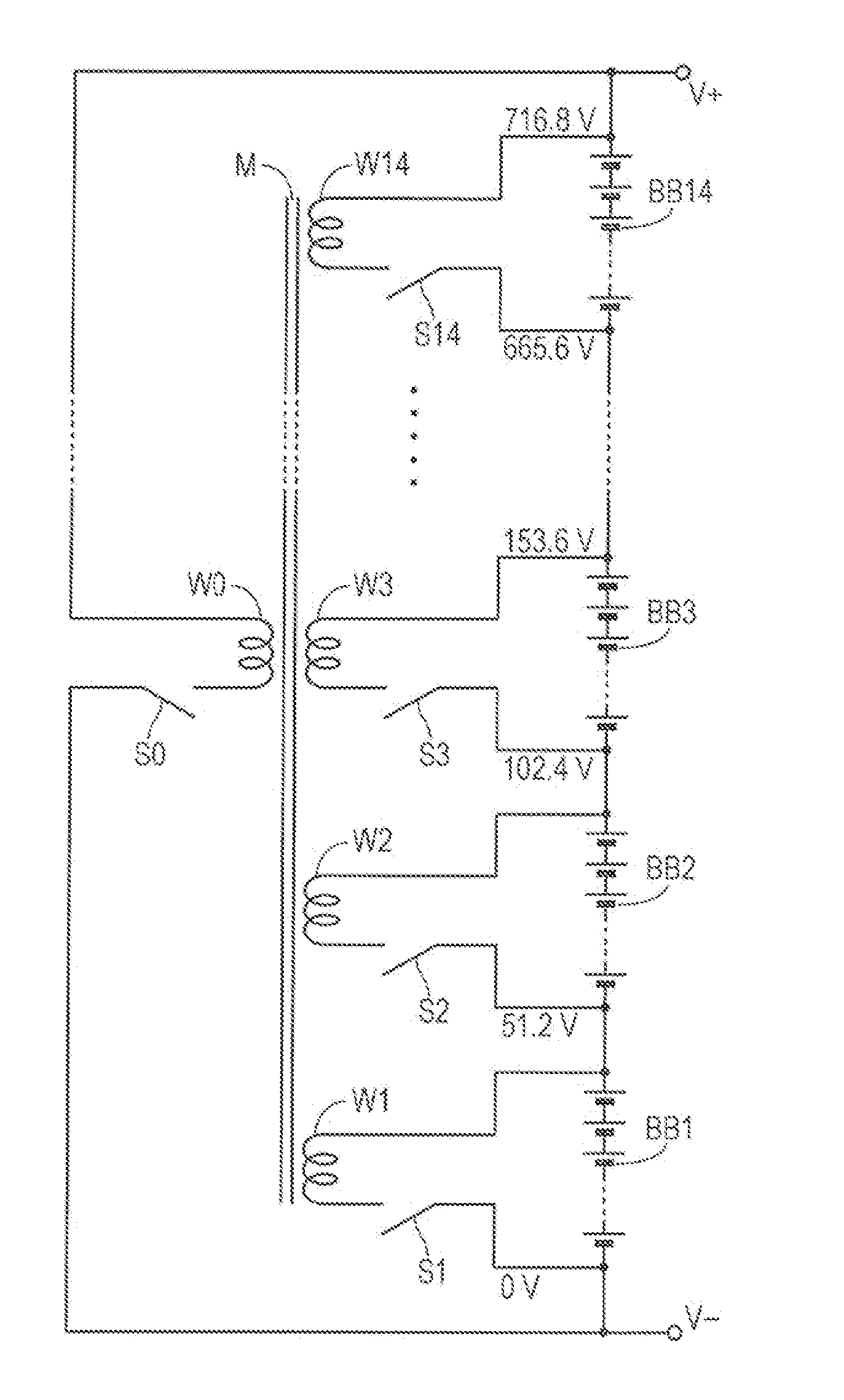
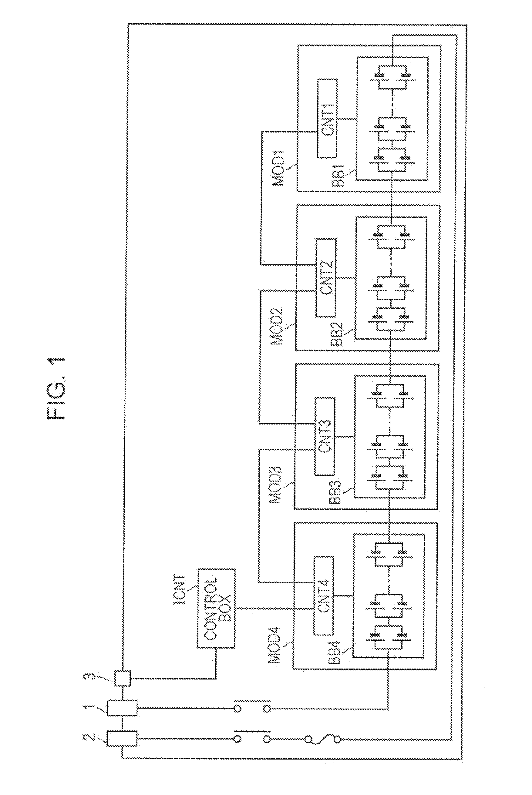
[0044]When a large number of power storage elements, that is, for example, battery cells, are used to generate high power, a configuration is adopted in which a plurality of power storage units (hereinafter referred to as the power storage modules) are connected to one another and a control apparatus is provided for the plurality of power storage modules in common. Such a configuration is referred to as a power reserve apparatus.

[0045]Each power storage module is a unit obtained by combining a battery unit including a series connection of a plurality of battery cells, that is, for example, lith...


PUM


Abstract

A power reserve apparatus is disclosed. In one embodiment, the power reserve apparatus comprises a first module including a first set of battery cells and a first inter-cell balance adjustment unit configured to use passive balancing to reduce voltage variance among the first set of battery cells. The power reserve apparatus also comprises a second module including a second set of battery cells and a second inter-cell balance adjustment unit configured to use passive balancing to reduce voltage variance among the second set of battery cells. The power reserve apparatus further comprises an inter-module balance adjustment unit configured to use active balancing to reduce voltage variance among the first and second modules.

Description

TECHNICAL FIELD[0001]The present disclosure relates to a power reserve apparatus, a power system, and an electric vehicle that utilizes power from the power reserve apparatus.BACKGROUND ART[0002]In these years, the usage of a secondary battery such as a lithium-ion battery is rapidly expanding to a power storage apparatus for reserving power and a power storage battery for a car combined with a new energy system such as a solar cell or wind power generation, and the like. When a large number of power storage elements such as, for example, unit batteries (also called electric batteries or cells; in the following description, referred to as battery cells as necessary) are used to generate high power, a configuration in which a plurality of power storage modules are connected in series with one another is adopted. In the power storage modules, a plurality of, that is, for example, four, battery cells are connected parallel to, and / or in series with, one another to configure a battery b...

Claims


Application Information

Patent Timeline
Patent Type & Authority Applications(United States)
IPC IPC(8): H02J7/00B60L3/00H02J7/02
CPCH02J7/0016H02J7/0021H02J7/025H02J7/0014H02J7/0054H01M10/441H01M10/46H01M10/482H01M2010/4271H01M2220/20B60L58/12B60L58/22Y02T10/70Y02E60/10H02J50/10H02J50/60H02J7/342H02J7/0019
Inventor SUGENO, NAOYUKISATO, MORIHIKOUMETSU, KOJI
Owner MURATA MFG CO LTD
Why Eureka
Try Eureka