
Electromagnetic opposing field actuators

a technology of opposing field and actuator, which is applied in the direction of magnets, relays, magnetic bodies, etc., can solve the problems of affecting the actuation frequency of hydraulics and pneumatics, requiring heavy and bulky pressure sources, and noisy typical noise, and achieves a long (high strain) bidirectional stroke. , the effect of high uniform for

Active Publication Date: 2014-12-04
ACTIVE SIGNAL TECH
View PDF18 Cites 56 Cited by
  • Summary
  • Abstract
  • Description
  • Claims
  • Application Information

AI Technical Summary

Benefits of technology

This invention is about new ways to create electromagnetic actuators that have a long stroke, high force, and are safe and reliable. These actuators have a unique design and construction method that makes them simple and efficient. They also have advantages like being able to generate a null or cancellation field, which reduces magnetic field loss and increases the effectiveness of the actuator. Overall, this invention provides a better way to create these actuators and makes them more suitable for use in various applications.

Problems solved by technology

However, these are typically noisy and require heavy and bulky pressure sources such as motor driven pumps, reservoirs, accumulators, manifolds, complex servo valves, cooling equipment and plumbing.
In addition, the actuation frequency of hydraulics and pneumatics is limited by valve dynamics and mass flow properties of liquids and gases.
Simple solid state actuation devices such as magnetostrictors, piezoelectrics and electrostrictors offer outstanding force capability (stress) but their strain output is so limited that it becomes extremely difficult to realize macroscopic strains in practical devices.
Practical real world strains to produce useful macro-scale work can therefore only be obtained with huge solid state devices or motion amplification mechanisms that introduce phase lag as well as mechanical energy losses that generally appear as backlash and hysteresis.
However, the performance of these devices does not extend into higher stress capabilities.
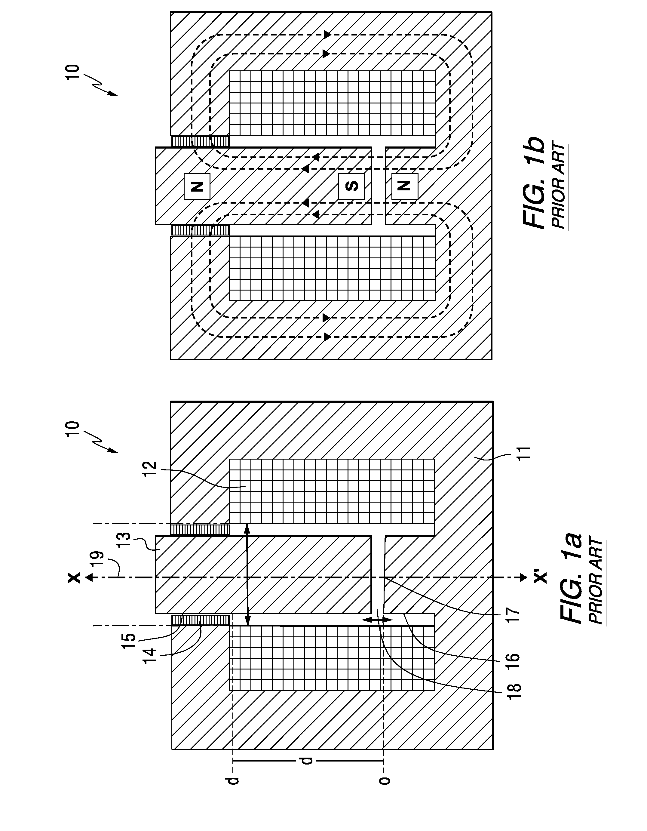
In addition, these devices produce highly non-uniform forces over their displacement ranges because their construction is constrained by the need for very high local magnetic fields.
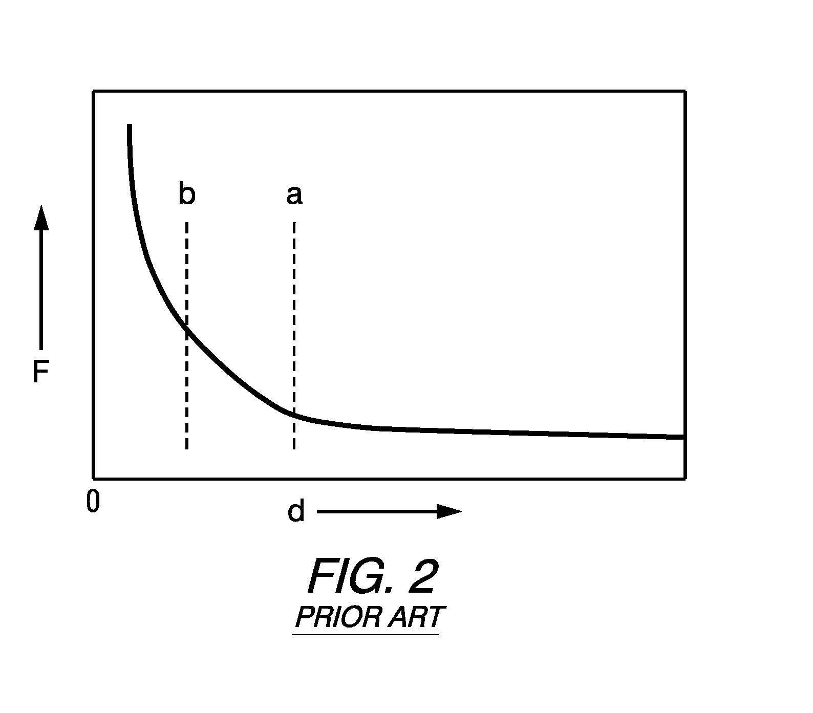
In both cases, the output force versus distance traveled by the moving element in the devices exhibits a nonlinear force versus distance behavior and consequent limitation on the range of useful displacement they can achieve.
Accordingly, if the coil support consumes space that would otherwise be occupied by coil windings or increases the size of gap in the magnetic circuit the capabilities of the device are compromised.
While the empty spaces, or voids, in moving coils are not configured in precisely the same way as those in solenoids, in both cases they present significant limitations on device performance.
However, such prior art DLEA devices present a control challenge when accurate forces and positions are needed with minimal overshoot and correction.
Two further control difficulties arise with the solenoid.
First, its intrinsic unidirectional force and hence return-spring mode of operation for reverse motion confers an entirely different force-distance profile and force-current (or voltage) profile in either direction.
Secondly, the ascending force versus current (or voltage) path and the ascending force versus distance path will differ from the corresponding reverse (or descending) paths giving rise to hysteresis (an effect that also varies with frequency) and hence ambiguity in determining the instantaneous state of the system.
Both options result in increased electrical and control complexity as well as greater size and weight.
The alternatives utilizing ancillary gears or ball-screws also present a finite risk of jamming failure as compared to the neutral, non-catastrophic graceful failure modes that can be invoked with hydraulic actuation systems, which is critical for high-reliability applications such as aircraft flight controls.

Method used


Image

  • Electromagnetic opposing field actuators
  • Electromagnetic opposing field actuators
  • Electromagnetic opposing field actuators

Examples


example 1

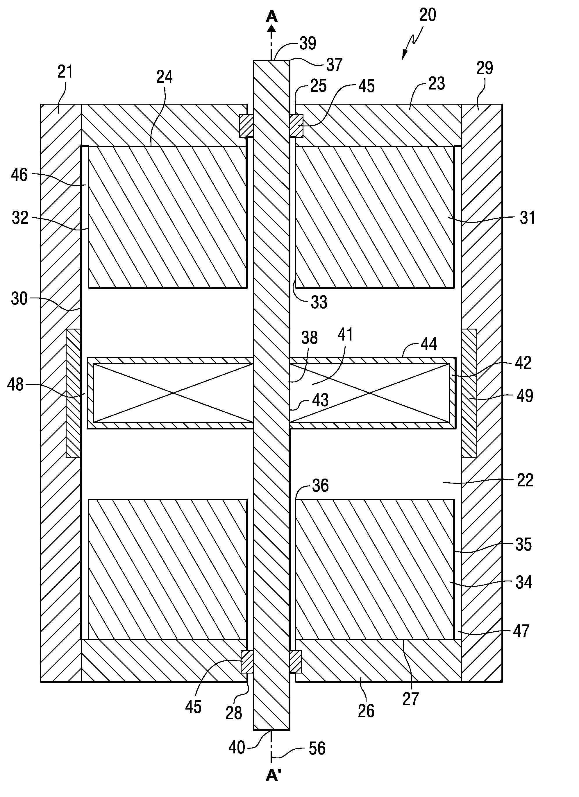
[0163]Example Device A, was constructed using a 416 stainless steel main housing with outer diameter of 1.5 inches, total housing length of 1.622 inches, and a wall thickness of 0.12 inches. This device was constructed with two cylindrical field magnets made from NdFeB 1.2 inches in diameter and 0.390 inches thick with a 0.24 inch diameter hole in the center, magnetized through the thickness to 44MGOe. The field magnets are mounted within the housing with a working gap of 0.620 inches between the inward facing opposing poles. Within the ID of the housing, there is a recess cut into the wall of the housing for a ring formed by 8 curved focus magnet segments which are 0.040 inches thick and 0.310 inches high. The center of this recess is located at the center of the working gap of the field magnets. The focus magnets are mounted within the housing such that their inward facing surfaces are flush with the adjacent inside diameter of the housing. The focus magnets are made from NdFeB se...

example 2

[0175]Example Device B was constructed with different dimensions from Example Device A. Example Device B weighed 2.1 kg, measuring 7.2 cm long, 7.6 cm diameter, generating a bidirectional symmetrical working stroke of 1 cm with a continuous linear force output rating up to 130N and an impulse rating of 900N (2 second intervals) with a frequency response of 100 Hz.

example 3

[0176]A family of seven devices are designed and modeled based on a 3 inch outside diameter housing for a device similar to the device shown in FIG. 3 with actuation ranges of 2 mm to 5 cm to demonstrate the range of actuation parameters obtainable within a limited design envelope. For this example the size and power of the field magnets as well as the size, number of turns, and power applied to the coil are all held constant. The thickness of the housing is held constant to the extent possible while allowing minor variation to accommodate the focus magnets. These devices are designed with a 416 stainless steel housing having an ID of 7 cm (2.75 inch) and a nominal outer diameter of 8.4 cm (3.3 inch) with a typical wall thickness of 7 mm (0.275 inch). The length of the housing is varied to accommodate the actuation distance as required, and the outer diameter increases slightly in the cases with longer actuation distance to accommodate the focus magnets. This device is constructed w...


PUM


Abstract

Electromagnetic actuators capable of generating a symmetrical bidirectional force are disclosed. The electromagnetic actuators include a housing made of a ferromagnetic material and a shaft made of a magnetically inert material movable along an axis within the housing. In one type of actuator, captive permanent magnets are arranged on opposite interior end walls of the housing and an electromagnetic coil is mounted on a central portion of the shaft. The electromagnetic coil is capable of generating a force when energized that causes linear displacement of the shaft in either direction along its axis depending on the direction of current through the electromagnetic coil. In another type of actuator, captive electromagnetic coils are arranged on opposing inner end walls of the housing, and a permanent magnet is mounted on a central portion of the shaft. The electromagnetic coils are capable of generating a force when energized that causes linear displacement of the shaft in either direction along its axis depending on a direction of current through the electromagnetic coils.

Description

CROSS-REFERENCE TO RELATED APPLICATIONS[0001]The present application claims priority to U.S. provisional patent application 61 / 927,841, filed on Jan. 15, 2014, and U.S. provisional patent application 61 / 828,378, filed on May 29, 2013, which are hereby incorporated by reference in their entirety.FIELD OF THE INVENTION[0002]The present invention relates to electromagnetic actuators, and more particularly relates to electromagnetic opposing field actuators that exhibit bidirectional action with a uniform force across a displacement distance, and a linearly proportional force to an applied current.BACKGROUND INFORMATION[0003]Linear actuation is very important in fields ranging from transportation, to controls, robotics and weapon systems. When considering the broadest range of linear actuators available to a mechanical design engineer, it is apparent that hydraulics and pneumatics offer unparalleled stress (defined as maximum force divided by actuator cross sectional area) and strain (e...

Claims


Application Information

Patent Timeline
IPC IPC(8): H01H50/20H01F7/02H01H50/44H01H50/04
CPCH01H50/20H01H50/44H01F7/02H01H50/04H01F7/066H02K33/18H01F7/122H01F7/13H01F7/1646H01F7/081
Inventor KOHLHAFER, DENNIS JOHN
Owner ACTIVE SIGNAL TECH
Learn More