Method of marking material and system therefore, and material marked according to same method

a marking system and material technology, applied in the field of providing a marking on solid materials, can solve the problems of unfavorable viewing, impact on the integrity and quality of gemstones, and gemstone devaluation, and achieve the effect of no loss in solid state material mass

Active Publication Date: 2014-12-04
CHOW TAI FOOK JEWELLERY CO LTD
View PDF3 Cites 0 Cited by
  • Summary
  • Abstract
  • Description
  • Claims
  • Application Information

AI Technical Summary

Benefits of technology

[0052]The system is adapted so as to maintain the integrity of said solid state material during formation of th

Problems solved by technology

For ornamental gemstones, the marking technique should not be visible to the naked eye so as not to detract from the quality of the stone from an aesthetic standpoint, whereby visible identification of marking may detract from the visual result in devaluation of a gemstone.
The tech

Method used


Image

  • Method of marking material and system therefore, and material marked according to same method
  • Method of marking material and system therefore, and material marked according to same method
  • Method of marking material and system therefore, and material marked according to same method

Examples


Embodiment Construction

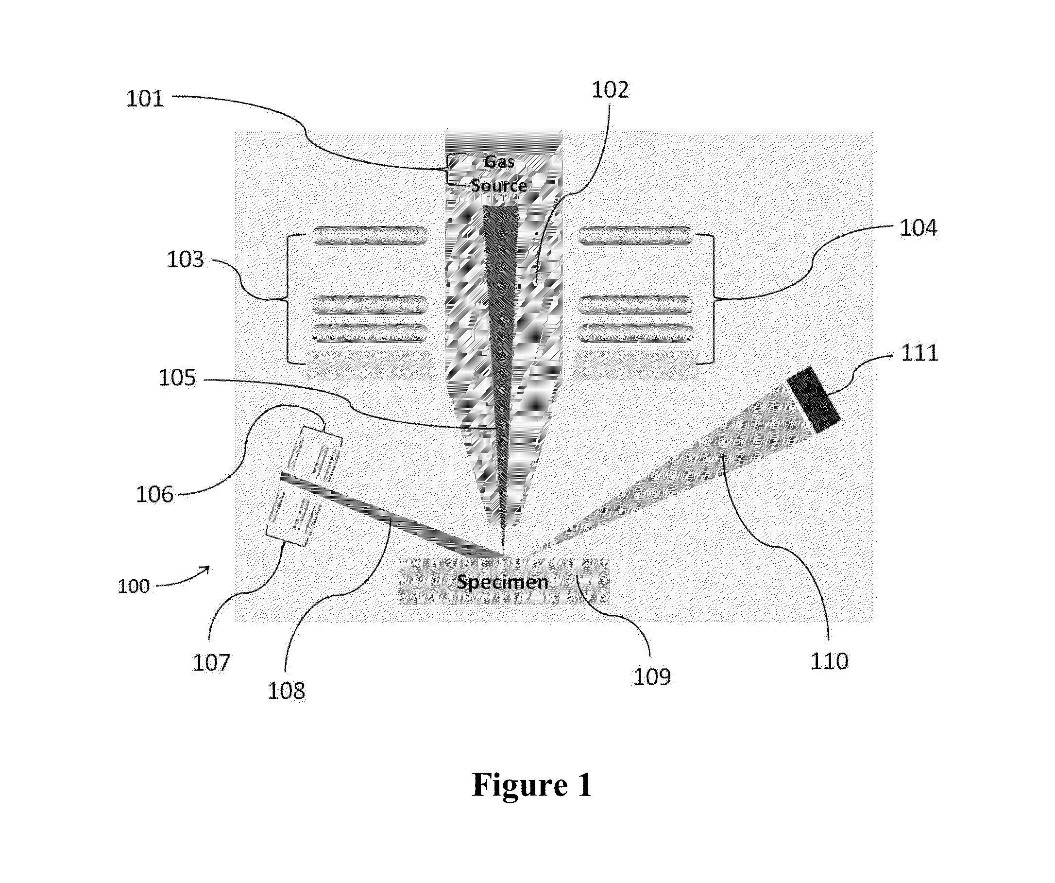
[0069]Referring to FIG. 1, there is shown an exemplary schematic diagram of a configuration of a focused inert gas ion beam system 100 as utilised in accordance with embodiments of the marking method of the present invention.

[0070]In comparison to typical scanning electron microscopy (SEM), the focused inert gas ion beam system 100 has a similar basic configuration, whereby the schematic diagram of FIG. 1 shows the configuration of a focused inert gas ion beam system 100 for producing and imaging the protruded array of nanometer sized dots in accordance with embodiments of the present invention is shown.

[0071]The gas sources 101 at the top of the electrostatic lens column 102 may be any known inert gases in Group VIII of the periodic table, and the choice of inert gas sources utilised depends on the requisite resulting resolution and fabrication time. Further, an inert gas is preferably utilised in order to minimise any alterations in electrical, optical, or chemical properties of a...


PUM


Abstract

A method of forming one or more protrusions on an outer surface of a polished face of a solid state material, said method including the step of applying focused inert gas ion beam local irradiation towards an outer surface of a polished facet of a solid state material in a way of protruding top surface material; wherein irradiated focused inert gas ions from said focused inert gas ion bean penetrate the outer surface of said polished facet of said solid state material; and wherein irradiated focused inert gas ions cause expansive strain within the solid state crystal lattice of the solid state material below said outer surface at a pressure so as to induce expansion of solid state crystal lattice, and form a protrusion on the outer surface of the polished face of said solid state material.

Description

FIELD OF THE INVENTION[0001]The present invention relates to a method of providing a marking on a solid state material. In particular, the present invention relates to providing a marking on a surface of a solid state material such as a gemstone or the like, whereby the marking is not optically viewable.BACKGROUND OF THE INVENTION[0002]Marking of solid materials, in particular precious gemstones or the like, may be required for example in identification or quality markings. For the marking of gemstones, it is desirable that marking be performed in a manner such that the gemstone is not damaged or any damage is minimised, the integrity of the gemstone is preserved, no significant loss in mass occurs, no chemical residue remains, and the marking does not detract from the clarity or colour of the gemstone.[0003]For ornamental gemstones, the marking technique should not be visible to the naked eye so as not to detract from the quality of the stone from an aesthetic standpoint, whereby v...

Claims


Application Information

Patent Timeline
IPC IPC(8): B01J19/08
CPCB01J19/081C30B29/04C30B29/16C30B29/20C30B29/34C30B33/04B41M3/14H01J37/317H01J2237/31713H01J2237/31737Y10T428/24355H01J37/00
Inventor HUI, KOON CHUNGCHING, HOKONG, CHING TOM
Owner CHOW TAI FOOK JEWELLERY CO LTD
Why Eureka
Try Eureka